I was kidding, people get so lost in the idea they are perfect.
Dc stability and current sharing never changed , often worse.
Hitachi seemed to know what they are doing. So they included them for parallel devices.
Dc stability and current sharing never changed , often worse.
Hitachi seemed to know what they are doing. So they included them for parallel devices.
The drain resistors are often placed there also to provide a measuring point for the bias current. You can put resistors at the source, measure the current (and adjust it with a VR if you have one) then take them off or short them with jumpers. How would you measure the bias current without a resistor?On the Hitachi Mosfet data sheet (Hitachi was one of the first, maybe the first, company to have introduced on the market this kind of components) they use a 0.2Ω resistor on the source of the MOS, so there must be a reason.
My 2 cents
The resistors are on the source lead to minimize thermal runaway which is positive up to about an amp.
Measurement without resisitors at the Lateral Mosfet is no problem. You have to put resistors into the voltage rails after supply and measure the drop of voltage.
1. you will need 2 nos. of 10ohm 1W/2W resistors.
1a. turn the trim pot so that resistance between first and third leg of trimmer is approx 250 ohm.
2. Connect one lead these 10ohm resistors in series with your + and - rail wires of psu.
3. connect the other lead of resistors to amplifier +/- supply connector on amp pcb.
4. switch on supply and measure the voltage drop across these rail resistors.
4a. measure the voltage between spk out and ground. this is offset. it should be less than +/-30mV. Good matching of Hfe of i/p transistor pair (Q1/Q3) will ensure that offset is close to zero.
5. total quiescient current is given by I= V/10ohm
6. set the pot so that voltage drop across 10 ohm rail resistors is about 1V to 1.1 V.
7. Let the amp warm up for 1/2 an hour recheck the bias
8. Adjust pot if required to have voltage drop of 1 to 1.1 V.
9. This will ensure that you get a bias through o/p stage of approx. 100mA.
Prasi has wrote this for the Apex FX8 if i rember right...you can do with other amps too...The FX8 has no drain resistors, but you can put it in.
Like in the old Elektor Mini Crescendo or Crescendo. There is no difference if using 0,22 Ohm or 0,2 Ohm. Elektor had paralleld 5 resistors 10 Ohm
to get 0,2 Ohm (see Hitachi). In these early years, 1984-1989, there was no chance to buy MCP resistors or similar.
More important is to use non inductive resistors. But these are older Lateral Mosfet.
With newer vertical mosfet you will need drain resistors to provide thermal problems.
My 2 cents...
Pedda
Don't use them! The sound will be infinitely better 🙂 Just make sure there are no oscillations / sudden variations in quiescent currents.
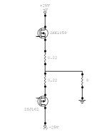
You should use 2 0.22 Ohm resistors connected like circuit 1. It has a lot of meaning in that circuit.Hello, I have a question.
I am designing a push pull audio amplifier with 2SK1058 and 2SJ162 mosfets.
Normally they are used with a 0.22Ω source resistors.
What about to put these 0.22Ω resistors connected to the drain?
ThanksView attachment 1371362View attachment 1371363