Hi all,
Instead of using fuses in the amplifier rails, I would like to use MOSFET switches as shown in: A DC Fault Protection Circuit for Audio Amplifiers
This way, I can use a micro-controller to disconnect the rails under various fault conditions (DC offset and current over-limit etc...)
The switching part is easy, but I also would like to use the RDS(on) value of these FETS in Isense circuits across both rails.
The MAX4080 would be OK for this purpose for the +ve high-side rail. Does anyone know if you can use this device to sense the -ve rail as well, or if not - another similar device for -ve voltages > 60V?
The device requires a differential input sense voltage that equals the rail voltage since the FETS are begin used as switches. Many devices only handle up to around 800mV.
Thx
I believe that most of these are used for motor control and similar single-ended power circuits, so the assumption is that you never have to shift a sense signal upwards. You shift a high-side sense signal downwards and do all the logic at the bottom of your supply range. So you put a simple op-amp around the low-side FET and the MAX4080 around the high-side FET and have your two sense signals centred around -Vcc. Bit of a problem with the small Vcc limit (75V) on the MAX4080. You might need more like a 150V device if you want to run +-70V rails, but you'll still be stuck doing all the sense signal-processing at -Vcc instead of around ground.
Any chance you can run a boosted supply above +Vcc and have the output of the sense-amp be digital? That way you can use opto-coupled outputs from your sense circuits, do lots of other interesting control (a micro, etc) around ground and then go opto-coupled again to the gate drives.
Any chance you can run a boosted supply above +Vcc and have the output of the sense-amp be digital? That way you can use opto-coupled outputs from your sense circuits, do lots of other interesting control (a micro, etc) around ground and then go opto-coupled again to the gate drives.
You could use a RR input comparator on each rail :
quick product list
Those would need a local power supply, fortunately if you pick one with low supply current, a zener and resistor will do.
Speed is very important to protect against short circuits. Software is too slow for this, a simple flop is a much better option.
quick product list
Those would need a local power supply, fortunately if you pick one with low supply current, a zener and resistor will do.
Speed is very important to protect against short circuits. Software is too slow for this, a simple flop is a much better option.
Last edited:
Why to use mosfet as electronic fuse only if you can make full protection power supply.
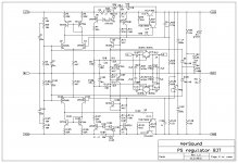
Here is schematic of my power supply regulator(regulator not stabilizer as it acts as a kind of capacitance multiplier) with all protection you need, electronic fuse with regressive delay and loudspeaker protection against DC on power amp output. I use it in my TT amp daily and it works as it was designed. In case of high voltage transients at the power amp input it will switch the electronic fuses off, and all you need is to switch off the power and wait to reset electronic fuse. I use BJT as regulating and fuse element but it's easy to change it to mosfet.
Here is schematic of my power supply regulator(regulator not stabilizer as it acts as a kind of capacitance multiplier) with all protection you need, electronic fuse with regressive delay and loudspeaker protection against DC on power amp output. I use it in my TT amp daily and it works as it was designed. In case of high voltage transients at the power amp input it will switch the electronic fuses off, and all you need is to switch off the power and wait to reset electronic fuse. I use BJT as regulating and fuse element but it's easy to change it to mosfet.
Attachments
I might have asked this question earlier but what is the maximum current through this regulator and what is the dissipation with component values as shown? Is it possible to parallel the power devices for more current?
Thanks.
Thanks.
I might have asked this question earlier but what is the maximum current through this regulator and what is the dissipation with component values as shown? Is it possible to parallel the power devices for more current?
Thanks.
The maximum current is set with series resistors R9, R109, and it will switch off faster at higher current, I don't remember exactly the value and in this case I think it's about 10 A. And of course it is possible to parallel the power devices for more current.
protection
Regards.
Thimios.
Hi dear , where can i find pcb for this power supply circuit?Why to use mosfet as electronic fuse only if you can make full protection power supply.
Here is schematic of my power supply regulator(regulator not stabilizer as it acts as a kind of capacitance multiplier) with all protection you need, electronic fuse with regressive delay and loudspeaker protection against DC on power amp output. I use it in my TT amp daily and it works as it was designed. In case of high voltage transients at the power amp input it will switch the electronic fuses off, and all you need is to switch off the power and wait to reset electronic fuse. I use BJT as regulating and fuse element but it's easy to change it to mosfet.
Regards.
Thimios.
Last edited:
Hi dear , where can i find pcb for this power supply circuit?
Regards.
Thimios.
Here, but it is older version with no master slave behavior of the output voltage.
http://www.diyaudio.com/forums/solid-state/182554-thermaltrak-tmc-amp-18.html#post3181253
A uC can definitely react to DC offsets by switching FETs off faster than switching a relay in the speaker line (uS vs ~15ms) and also removes the problem with inductive arcing and damaging relay contacts. Fault currents can still be detected in microseconds and can easily be as fast as a fuse depending on the fuse I2t rating and the fault current.
One major issue with FETs is that if they do blow they normally blow shorted - which isn't good news.
I think the easiest way to detect over current is a comparator local to each rail and detected through an opto.
Any existing circuits for this idea so I don;t have to reinvent it?
One major issue with FETs is that if they do blow they normally blow shorted - which isn't good news.
I think the easiest way to detect over current is a comparator local to each rail and detected through an opto.
Any existing circuits for this idea so I don;t have to reinvent it?
A uC can definitely react to DC offsets by switching FETs off faster than switching a relay in the speaker line (uS vs ~15ms) and also removes the problem with inductive arcing and damaging relay contacts. Fault currents can still be detected in microseconds and can easily be as fast as a fuse depending on the fuse I2t rating and the fault current.
One major issue with FETs is that if they do blow they normally blow shorted - which isn't good news.
I think the easiest way to detect over current is a comparator local to each rail and detected through an opto.
Any existing circuits for this idea so I don;t have to reinvent it?
Agree that micros are definitely fast enough; the limiting factor is the analogue nature of fault detection and how DC doesn't look very different from 15Hz at full power - you can't detect that any faster than 1/30s, probably more like 1/10s, unless you want false triggering at full power. You can detect rail-to-rail shorts in microseconds though because their current is not limited by the speaker. Anyone who thinks a micro is 'too slow' compared to a fuse or relay is confused by a couple of orders of magnitude.
You can avoid avalanche failure by putting 2 FETs in series in each rail (so four total per double-ended supply) and then a big fast reverse diode around the two of them which will take all the inductive energy from the speaker in preference to the FET's body diodes because it has about half the junction voltage of the series FETs.
My only concern with a series FET in the rails is that it could well fuse short before the failure is detected and gate drive is removed; it's not an issue for speaker protection because the speaker limits the current to much less than what the FET can take even in the long term. You'd need to do some screwdriver testing to make sure of the circuit's reliability in the face of hard shorts.
Over current can be caught pretty much instantaneously (within micro-secs). DC offset is based off the LPF of the detector and has normally ~50-100ms detection time - so in the DC case, micro-secs to turn the rails off is a moot point w.r.t speed of detection.
I was planning on using something like these: Invalid Request
I was planning to 2 x parallel them (circa 190A) to give robust current handling in case of a dead short and delayed reaction from any Isense circuit. Amplifiers normally have catch diodes at the speaker terminal which would do the same as the reverse diode across the FET (unless I am mistaken...) The rest of the circuit has some decoupling, but not much energy there.
Yes - the screwdriver test will be a necessity (probably blow a few tracks off the board in the process!!)
I appreciate all the input.....
Thanks JasonP for finding this important article. I had thought before this, based on date of post on diyaudio.com, that Michael Bean invented the use of MOSFETs driven by photovoltaic optoisolators as speaker shutoffs. I though I was breaking ground to use a single FET powered by a single optoisolator to shut off each rail, I'm happy to see I am not.
I'm building a rail shutoff circuit for an amp that has a rail crowbar triac that melts the PWB land off the board instead of blowing the main breaker. I think using open collector or logic is sufficient to trip the off state on various faults, no programming software required. My base shutoff is the presence of DC on the speaker terminal longer than a certain period, ie the SPS (diac) in series with a resistor and capacitor, to provide current to a shutoff mechanism.
A second fault detect mechanism may be excessive current through a NTC resistor attached to the heat sink with the output transistors on it. This would replace the "way too late" thermal snap action thermostat the amp designer attached to an output transistor with the speaker current running through it. This would provide detection if the fan stops spinning, for example.
I currently have 25 A 32 V fuse in series with the shutoff FET on each rail, but have my doubts about the sonic invisibility of a tin plate brass fuse clip on a tin plate copper fuse ring at low wattage, say 1/8 watt. At least these rail fuses are outside the feedback loop. Looking forwards, instead of sensing the FET voltage, which is highly non-linear and temperature sensitive, I'm looking at sensing the voltage across the output transistor emitter resistors. An overcurrent condition out the speaker terminal would cause excessive voltage there, stressing the output transistors but having a definite signature that can be analog processed. My amp already has a sense circuit, three 2200 ohm resistors connected across the five emitter to emitter resistor junctions, which goes to a "VI" limiter which cuts the base drive to the predriver transistor. I'm thinking of rectifying this signal with a double schottky diode, feeding through a high value resistor and parallel capacitor to ground to an op amp input, which input bleeds off to ground though a higher value resistor. I don't want one musical peak to blow the circuit. If the op amp used as a comparator senses too much emitter current over a time, the open collector or on the protection circuit is pulled to ground and the rail voltage shuts off. Since my amp with five pairs of output TO3 transistor is rated to drive 2 ohm loads, I'm thinking of calibrating the speaker overcurrent protection circuit with a 1 ohm load on the speaker terminal.
Dadod's circuit is interesting, but with 1 output transistor on each rail, doesn't offer enough current capability for my amp with possible normal 22.5 amp speaker currents. Dadod's circuit also drops a lot more rail voltage as heat, compared to a couple of FETs at 0.2 ohms or less. Looking at the tables, I think using a
APV1122 optoisolator to drive one FDP52N20 transistor should max out at 0.1 ohm, hopefully better
Last edited:
I was planning to 2 x parallel them (circa 190A) to give robust current handling in case of a dead short and delayed reaction from any Isense circuit. Amplifiers normally have catch diodes at the speaker terminal which would do the same as the reverse diode across the FET (unless I am mistaken...) The rest of the circuit has some decoupling, but not much energy there.
I don't think paralleling them will help - if you short that FET across 15,000uF at 70V then the current is going to be in the kA range pretty quickly, especially since you made sure your wiring from the main C to the amp board is low-L, right? 🙂 You put two in parallel, you're just going to double the total current and you'll get four molten puddles of glass instead of two 🙁
The exact placement of the catch diodes is interesting. If they go from (hot) speaker terminal to each Vcc after these FETs, they're effectively in series with these FETs so when you open the FET to protect the speaker from DC, the inductive energy will be dumped through the catch diodes and the FET body-diodes into the main capacitors and therefore the body diode's avalanche rating has to be big enough to withstand that.
If, alternatively, you put the catch diodes from the hot output to before these FETs (between main-C and FET), then some of the inductive energy has the opportunity to bypass the FET body diodes depending on the relative junction voltages of the FET diodes and your chosen catch diodes. Series FETs will double the Vf of that path and force hopefully all of the inductive kick through the catch diodes and directly into the main caps, with little or no avalanche energy delivered to the FETs. In that case, I think your FET is guaranteed to survive if it doesn't melt before you remove gate drive. It means the FETs can't protect against a short across the catch diodes though, if you care.
What about series protection FETs and a fat oversized fuse (20A+) in series? If the FETs fail due to a really bad short then it's probably already way too late for the output stage (if the current is going through it) and the fuse will hopefully prevent capacitor damage and/or fire. As indianajo points out, this is all outside/before the feedback so I really struggle to believe you'd hear the fuse.
I do also like the crowbar plus driver-stage-mute option frequently advocated by ThorstenL in the Output Relays thread. It also depends on a fat fuse that can be blown with a triac, but should only blow it if there is a short across the output stage. An external output short, presence of DC or exceeding SOA should just cause the amp to shut down. Implementation I think just needs two or three triacs: one for the EF input (two if you put it them after the Vbe multiplier) and one for the output hot.
Last edited:
On second thoughts, inductive kick is not a problem. There might be 0.5J in the speaker coil but when it's dumped into capacitor at 50V+ and there's maybe 1.2V across the body diode, 98% of the energy is going into the C not the FET. The energy absorbed by the body diode is tiny fraction of the FET's avalanche energy capacity. Crowbarring across the woofer with a FET would stress the FET, but we're not doing that.
So you can ignore my waffle above about catch diode placement. They go after the FETs, directly across the output stage, and are therefore also protected by the FETs.
So you can ignore my waffle above about catch diode placement. They go after the FETs, directly across the output stage, and are therefore also protected by the FETs.
My PV-1.3k had crowbar+driver stage compression. It also had burned lands to the triac, and 19 of 20 output transistors blown, when I bought it. When I patched the circuit board with a half inch of 16 ga wire, and another OT blew, it burned that 16 ga wire in two, also. I view this crowbar circuit as a big failure. The fuse between output board and main cap makes it better, but if one blows the output immediately goes to 170 v the other way- no help really if the crowbar triac is already blown up. The FET has a chance of stopping the DC from getting out permanently with a flip flop remembering that the DC detect circuit found a fault. A fault LED is in series with the optoisolator energizer LED.I do also like the crowbar plus driver-stage-mute option frequently advocated by ThorstenL in the Output Relays thread. It also depends on a fat fuse that can be blown with a triac, but should only blow it if there is a short across the output stage. An external output short, presence of DC or exceeding SOA should just cause the amp to shut down. Implementation I think just needs two or three triacs: one for the EF input (two if you put it them after the Vbe multiplier) and one for the output hot.
And I don't see all the worry about the speaker inductance. Most of the time bands plugged the wrong 1/4 phone plug in the wrong hole in the dark, or tripped over the wire and pulled the 1/4 phone plug 1/4" out, creating a short circuit that bypasses the speaker. this bar band setup has all kinds of signs that wrong phone plugs went in wrong holes. Input resistors blown to cinders on another power amp, output op amps on the mixer blown to vapor, etc. If a speaker does lose the suspension, it might short one turn first, which would be an overcurrent situation, not a dead short like a phone plug out.
If you want to protect against a dead short, reaction time is important.
When the output terminals are shorted, what limits the rate of rise of the current is the inductance of all connections (and zobel if you got one).
Then, considering inductance and delay to switch off, you can calculate the max current the MOS will have to switch off. Switching time gives you the energy pulse dissipated in the MOS. Big MOS are slower to switch, the output current of the MOS driver must be considered too.
I've done a h-bridge with full protection, it will survive a screwdriver on the output. Protection reacts in about 500 ns. It uses a current sense, hardware comparator in uC, and hardware fault input to PWM unit in uC.
If your amp has output current limit, hopefully current will not rise to 1 kA even if the protection is slow. Then it must just react before the MOS which does the limiting overheats.
I did an oscillation detector also, on an amp, it was a simple slew rate comparator. RC highpass filter to a comparator with hysteresis (ie, a logic gate with a resistor across). This outputs a square wave if the amp outputs oscillates, a constant level if it doesn't.
That is a cool article from Electronic Design. All the complications seem to be in the auto-reset circuit., which I wouldn't use or want.
I was wondering in base rail disconnect per R.G. Keen, if the detect circuit turns off the photovoltaic isolator, how long the FET takes to shut off. The fet I am using the gate charge is 49 nano-coulombs, the photovoltaic optoisolator APV1122 has "turn off time of 0.1 ms with 1000 pf gate capacitance". The FET I'm using has 2900 pf of gate capacitance. the optoisolator photodiode short circuit drive current is 5 microA. I wonder if I should put a 1 meg resistor across the photodiode (and FET gate to source) to decrease turn off time? or is there a better way?
I was wondering in base rail disconnect per R.G. Keen, if the detect circuit turns off the photovoltaic isolator, how long the FET takes to shut off. The fet I am using the gate charge is 49 nano-coulombs, the photovoltaic optoisolator APV1122 has "turn off time of 0.1 ms with 1000 pf gate capacitance". The FET I'm using has 2900 pf of gate capacitance. the optoisolator photodiode short circuit drive current is 5 microA. I wonder if I should put a 1 meg resistor across the photodiode (and FET gate to source) to decrease turn off time? or is there a better way?
Last edited:
I was wondering in base rail disconnect per R.G. Keen, if the detect circuit turns off the photovoltaic isolator, how long the FET takes to shut off. The fet I am using the gate charge is 49 nano-coulombs, the photovoltaic optoisolator APV1122 has "turn off time of 0.1 ms with 1000 pf gate capacitance". The FET I'm using has 2900 pf of gate capacitance. the optoisolator photodiode short circuit drive current is 5 microA. I wonder if I should put a 1 meg resistor across the photodiode (and FET gate to source) to decrease turn off time? or is there a better way?
It seems to be down at the moment, but the Rod Elliott article on MOSFET speaker protection switches advocates using an additional small-signal FET between the photodiode isolator and the big FET. Gives you a couple orders of magnitude better turnoff speed by sinking the big FET's gate charge through the little FET I think, but I don't recall the exact circuit.
Hi,
You can use the ACS712 hall effect current sensor with the output feeding a comparator that enable or disable the output relay for the speakers or whatever you want to control. You can buy them in different current sizes. They come 5,12, 30,50 and 100 amps. Also you can buy them in a small daughter board than can be mounted in any place in the amplifier chassis.
You can use the ACS712 hall effect current sensor with the output feeding a comparator that enable or disable the output relay for the speakers or whatever you want to control. You can buy them in different current sizes. They come 5,12, 30,50 and 100 amps. Also you can buy them in a small daughter board than can be mounted in any place in the amplifier chassis.
Sorry - deleted by mistake
Electronic Design article here:
Resettable High-Speed Fuse Uses FET As A Sense Resistor | Components content from Electronic Design
This without the reset circuit would be ideal, but is low-side. Will take a better look over next few days and spice simulate a high side version.
Electronic Design article here:
Resettable High-Speed Fuse Uses FET As A Sense Resistor | Components content from Electronic Design
This without the reset circuit would be ideal, but is low-side. Will take a better look over next few days and spice simulate a high side version.
- Status
- Not open for further replies.
- Home
- Amplifiers
- Solid State
- MOSFET power supply switch with Isense