Hi all
I have just built a bread board class D amplifier, It works fine with bipolars on the output (npn and pnp), When i put mosfets on there it gives a wierd wave and starts misbehaving, I know this is due to the input capacitance of the mosfet. How can i simply get round this as i dont have a clue as to driving mosfets at high frequency.
The FET are
IRF530
IRF9530
The switching frequency is 200Hz and they are currently driving by the output of a comparitor, I have added a resisor and diode to give some dead time as they were getting hot.
Thanks
Rob
Hi,
Post your schematic..
It is very doubtful that your comparator will drive the mosfets directly.
You'll probably want to keep your previous NPN/PNP output stage as a low impedance buffer (high current driver), and use that to drive the gates, possibly each through a level shifting capacitor.
Good luck.
Chris
Hi there,
200Hz ? I do hope you meant 200Khz LOL
Post the schematic so we can help...
Regards
Mad.P
P.S Hope your not planning on plugging this one into the mains 😉
200Hz ? I do hope you meant 200Khz LOL
Post the schematic so we can help...
Regards
Mad.P
P.S Hope your not planning on plugging this one into the mains 😉
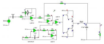
Well i dont have time to model it on LTspice but heres a simalar crocclips model, I have changed a few things such as
Due to the lm311 being a comparitor i have put a 1k resistor from the output of the LM311 comparitor to the +15v rail.
The component values on this are quite likly to be wrong but you get the idea, It is not the exact cicuit that i have built.
As for the output stage using transistor as is on the circuit the transistor output works but does not give a square wave, It has a dip in the middle of the wave. Does anyone know what that is?
When i put mosfets on it the whole thing gives a very odd wave shape.
What can i use to drive the mosfets as i assume i need lower output inpedance for the base of the mosfets to drive the capacitance.
I am using IRF530 and its complement.
Oh and yes i did mean 200KHz
- Status
- Not open for further replies.