Hi,
I came across slides from Bob Cordell showing details of the DH-220C amplifier. Those slides were presented during the Burning Amp convention 2016.
The output stage gate protection looks unusual. I'm pretty sure this circuit is superior to a simpler way like back to back Zeners, but I can't figure out why.
Somehow I feel stupid for asking because this is such a simple circuit, but can somebody more knowledgeable please explain it to me?
Why is this circuit any better than just back back Zeners between gates and source?
Thank you very much!
Attachments
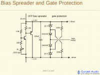
This circuit is described on p347 of Bob’s 2nd edition of designing audio power amps. It says the 220k resistors in the circuit provide about 2.7V of reverse bias to the zener diodes to reduce their capacitance
Last edited:
Thanks for your help.
I was expecting that it should work like this somehow.
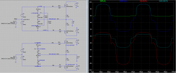
However, DC conditions imply that the Zener is not more reverse biased, but slightly more forward biased instead.
The normal diode is more reverse biased in turn and also subject to more voltage swing.
AC wise, the voltage swing across the Zener is lowered by applying some forward direction bias.
Less AC swing = less reverse capacitance variation = lower distortion?
I'm still puzzled TBH...
I was expecting that it should work like this somehow.
However, DC conditions imply that the Zener is not more reverse biased, but slightly more forward biased instead.
The normal diode is more reverse biased in turn and also subject to more voltage swing.
AC wise, the voltage swing across the Zener is lowered by applying some forward direction bias.
Less AC swing = less reverse capacitance variation = lower distortion?
I'm still puzzled TBH...
Attachments
Protection Latch
The positive feedback around the NPN and PNP forms a thyristor connected pair. Under overload this latches into the on state of about 1Volt and collapses the voltage from the bias spreader. The pot sets the latch trip point.
The positive feedback around the NPN and PNP forms a thyristor connected pair. Under overload this latches into the on state of about 1Volt and collapses the voltage from the bias spreader. The pot sets the latch trip point.
The pot sets the bias voltage for the output stage, which sets the bias current in the output devices.
The diodes clamp the voltage to avoid overdriving the gates and to limit the maximum current
More Details - The 1N4149 diode is 1/2 the capacitance of the 1N4148
The diodes clamp the voltage to avoid overdriving the gates and to limit the maximum current
More Details - The 1N4149 diode is 1/2 the capacitance of the 1N4148
Last edited: