It's the same configuration of devices, but driven in a different way: In single-ended class A, the lower current source is constant. In quasi-complementary push-pull class AB, the lower current source is modulated by the input signal.Bricolo said:upper transistor: follower
lower transistor: ccs
isn't that class a?
darkfenriz said:
Voltage source (follower) with current source (common source) in class (A)B simply doesn't make sense, what if I and V have phase difference of 40deg. ?
regards
Hi Darkfenriz,
Kindly,....Put some more details and so i can comment.....upon your post😉 ellaborate it in detail.....
K a n w a r
Hallo
both upper and lower devices work as current sources I think.
If it were voltage source with current source one would have to assume the load. If we want devices to switch on and off (class ab working) than the amp must know for what voltage to switch current source. First, obvious, wrong solution would be to switch on current source, when voltage has to be negative, but on reactive load sometimes voltage is negative and current positive and vice versa.
In contrary when both devices are current sources, then feedback corrects the output signal and whole amp is a voltage source, no problem with switching.
I just wouldn't call upper device a follower then.
best regards
yeah thats the way, you clarified it well...thanks...i agree with you.
BTW:why do many people write 'qu-asi-funny' stuff here?well you should know it very well😀
regards,
K a n w a r
BTW:why do many people write 'qu-asi-funny' stuff here?well you should know it very well😀
regards,
K a n w a r
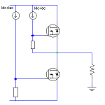
I've attached a diagram just to make sure everyone is talking about the same thing... The upper MOSFET output voltage 'follows' the input voltage. Thus it is a source-follower, or common-drain. This configuration has low output impedance, which means it is most conveniently thought of as a voltage source.darkfenriz said:Hallo
both upper and lower devices work as current sources I think.
If it were voltage source with current source one would have to assume the load. If we want devices to switch on and off (class ab working) than the amp must know for what voltage to switch current source. First, obvious, wrong solution would be to switch on current source, when voltage has to be negative, but on reactive load sometimes voltage is negative and current positive and vice versa.
In contrary when both devices are current sources, then feedback corrects the output signal and whole amp is a voltage source, no problem with switching.
I just wouldn't call upper device a follower then.
best regards
The lower MOSFET on the other hand is common-source, where the output is taken from the drain. This configuration has high output impedance, and so is best described as a current source.
Feedback, either local or global, will turn the amp as a whole into a voltage source, but the output stage is clearly not symmetrical on its own. That doesn't mean it will have any trouble with reactive loads, it just means the behaviour in each direction is different before feedback.
Attachments
No we weren't talking about the same thing, or no you disagree with my explanation?darkfenriz said:
Assuming it's my explanation you disagree with, perhaps I could convey my thoughts more clearly with slightly different diagram:
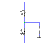
A) If the lower FET is fed by a constant voltage, then it's clearly a current source. If the upper FET is fed with the input signal, then the whole thing operates as single-ended class-A: upper device a voltage-follower, lower device a current source.
B) If instead, both FETs are fed with the input signal, then it's push-pull. The lower device is still a current source, but not constant...
Attachments
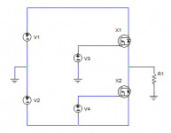
Here's the same output stage with a couple of extra devices added to turn it into a standard quasi-complementary topology. It's effectively the same as B) above, but now there is 100% local feedback around the lower device, making the output stage as a whole behave like a voltage source in both directions.
There are other ways of acheiving the same effect with only one polarity of output device, but no matter how you do it, inherently one output device is a voltage source and the other a current source.
There are other ways of acheiving the same effect with only one polarity of output device, but no matter how you do it, inherently one output device is a voltage source and the other a current source.
Attachments
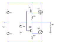
I know could deny my point, but N-channel topology is for me something different than darlington upper, sziklai lower (or fet equivalents), which is called quasi-complementary. You are right that lower device works in 100% local feedback in quasi, so it plays as if being a complementary device. That's what the term 'quasi-complementary' comes from.
In N-channel nothing's complementary, even quasi, as both devices work as current sources. It is a bit like vintage tube push-pull, but without transformer.
I attach the picture, which speaks for itself. Notice AC currents being of opposite sign. Diffenrential amplifier is most often used as phase splitter. In this topology output stage mosfets are driven by modulating G-S voltage- thus current sources. Agreed? 😉
regards
Attachments
Ok, I see what you mean. But I still contend that the upper device is a source-follower/common-drain, but its input voltage changes when the output tries to draw current through its gate-source resistor, causing its input voltage to change and its output voltage changes with it.
- Status
- Not open for further replies.
- Home
- Amplifiers
- Solid State
- MOSFET or NPN for class A output stage