That is really insane isn't it? I guess that is because it is a sim?The green line is a shunt regulator
Honestly, without seeing the psrr vs frequency, I can't make sense of those numbers; psrr and output impedance, as you know, deal with completely different causes of ripple.
That is really insane isn't it? I guess that is because it is a sim?
Yes, it is insane, and yes, it's a simulation. Very difficult in practice to achieve output impedance that is even remotely like this. However, this shows that the design isn't the limitation, and it's all in the building then. If the design is limited there is absolutely nothing one can do in practice to make it perform well.
I've built a version of this for low voltage, and some other people too, who have reported good results. Similar topology as this one.
That is what I thought. Pretty useless putting that in their brochure.Honestly, without seeing the psrr vs frequency, I can't make sense of those numbers;
Last edited:
Hey Bas,
Can do sim of PSRR of my simple circuit and the one you proposed initially at100Hz for you tomorrow. I remember this was in another thread awhile ago. Think I have the sims somewhere.
Can do sim of PSRR of my simple circuit and the one you proposed initially at100Hz for you tomorrow. I remember this was in another thread awhile ago. Think I have the sims somewhere.
That would be great...thanks.Can do sim of PSRR of my simple circuit and the one you proposed initially at100Hz for you tomorrow. I remember this was in another thread awhile ago. Think I have the sims somewhere.
Was wrong😱, found my old file and the gyrator and my circuit where close with the standard follower better. These curves are for 20V ptp 100Hz ripple in. Running 20kHz ripple the follower is a lot worse while the two other are equal.
Attachments
Thanks Lars!
So the old gyrator is not bad...because it has one less "active" part and comes close to your circuit.
So the old gyrator is not bad...because it has one less "active" part and comes close to your circuit.
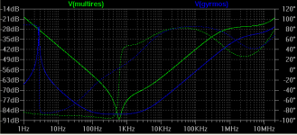
Hi Lars, it surprises me that your multires comes out better than gyrmos. My simulation of your circuits show a bit of a different story. Especially the .ac plot, see attached. I used the exact values you showed in your circuit. At 100-120Hz the psrr of gyrmos is quite a bit better. Am I missing something?
Edit: NB, with one change, I used an active load of 40mA DC instead of the passive resistor load.
Edit: NB, with one change, I used an active load of 40mA DC instead of the passive resistor load.
Attachments
Hi Lars, it surprises me that your multires comes out better than gyrmos. My simulation of your circuits show a bit of a different story. Especially the .ac plot, see attached. I used the exact values you showed in your circuit. At 100-120Hz the psrr of gyrmos is quite a bit better. Am I missing something?
Edit: NB, with one change, I used an active load of 40mA DC instead of the passive resistor load.
Hi,
The only difference is that I loaded the thing resistive with ca 110mA. Just tried with CCS of 110mA and get same result at 100Hz. Maybe LTspice is missing something😉.
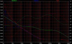
My sim tells another story than yours. Changed the seriesresistors to 33ohm. Don´t mind the dBscale its 20dB wrong.
Attachments
Last edited:
It shows about 10dB better psrr for gyrmos, at about 100-120Hz. The .trans show ripple though, is smaller for multires. That to me, is a bit odd.
Remember I changed from 10ohm to 33ohm. Before that multires was ca 2dB better than the other two at 100Hz.
Just realized that I have some of those because I got some extra for the Zen V9. 🙂 Way cheaper if I remember well. So I'll use those...much cheaper than the 20N50D.IRFP240
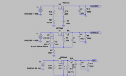
I'm working with mosfet gyrator by schematic as attachment
R1, R2 330k Ohm
C1 5.6uF
D1 ZD15
R3 150 Ohm / 5W
Q1 IRF840
At the moment , i want to get :
- Vout = 100VDC when Vin = 120 VDC ( after bridge rectifier)
The question is that how do I adjust R1, R2 to get exactly the above Vout voltage ? Pls kindly advise. Tks
R1, R2 330k Ohm
C1 5.6uF
D1 ZD15
R3 150 Ohm / 5W
Q1 IRF840
At the moment , i want to get :
- Vout = 100VDC when Vin = 120 VDC ( after bridge rectifier)
The question is that how do I adjust R1, R2 to get exactly the above Vout voltage ? Pls kindly advise. Tks
Attachments
The gyrator is not a regulator in the sense that it will have an absolute (exact) output voltage, so if you want exactly 100V at the output under different operation conditions, it will not work. Still, I think it is possible to accomplish a relatively constant output voltage in class A operation, but to do some calculations on it one needs to know how much current your circuit will be drawing (this current goes through R3, what causes a voltage drop... )
Another add-on question.
I am modelling the gyrator, prior to using it in a SE tube amp, 400V DC.
What I see is a great regulation.
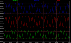
However, in the time domain (.tran 10sec uic) then I have an 'oscillation of the 100Hz that I add in the power supply (SINE(420 10 100)) and that oscillation stays for some 3 - 8 secs.
In case I load the gyrator with 47 uF then the oscillation is very strong (for 10 secs, slowly stopping) but with a 10 nF load it damps faster.
What do I do wrong?

Oh yes, and the oscillation gives a negative current too on the output resistor . .. 😱
- I have a input RC, 5 ohms, 33 uF, and that is the reason. Omitting it so C load = 10nF, all looks OK.
But the capacitor is needed to get the good working, that is, noise reduction of 60 dB.

I am modelling the gyrator, prior to using it in a SE tube amp, 400V DC.
What I see is a great regulation.
However, in the time domain (.tran 10sec uic) then I have an 'oscillation of the 100Hz that I add in the power supply (SINE(420 10 100)) and that oscillation stays for some 3 - 8 secs.
In case I load the gyrator with 47 uF then the oscillation is very strong (for 10 secs, slowly stopping) but with a 10 nF load it damps faster.
What do I do wrong?
Oh yes, and the oscillation gives a negative current too on the output resistor . .. 😱
- I have a input RC, 5 ohms, 33 uF, and that is the reason. Omitting it so C load = 10nF, all looks OK.
But the capacitor is needed to get the good working, that is, noise reduction of 60 dB.
Attachments
Bas, the simple schematic you posted first will work really well with the push pull BH amp.
I wouldn’t go any further than the schematic by Yves DuPont at the top of the page. That will reduce your B+ ripple to mv. Since you are building a small PP amp you may not have room for more complex circuitry that requires a pcb. Also PP amps have good ps rejection vs single ended and the BH driver uses a dif input stage with a current source and a mosfet buffer to drive the outputs. I don’t think you need to go to heroic efforts on the power supply. The law of diminishing returns has set in at this point.
You are more likely to have hum from induced voltages in a compact amplifier where you have a lot of transformers, perhaps ac filaments, etc packed into a small volume than from a properly designed HV power supply.
I got rid of that 100 Hz oscillation (the red flag in the picture above) on the load resistor with Rout = 33 ohm

Well, I am just playing lego, others might understand it.
Anyway, just solder it and see. The best thing to do. In practice, these problems probably do not exist.
In all cases the voltage output is OK on screen. Great even.
I now have a circuit with LND150 --> set resistor now to get a voltage reference, with the gate of IRF830 connected with a low pass filter 100k/1uF, it also works great by the way. No feedback with a capacitor: just a simple traditional voltage stabilizer. <5 mV output residue . .
- by changing the output resistances to 47 ohms in the sim.
- and the cap must be higher, such as 220uF
- and, having the divider end at the bottom of the Rout stops reduces the oscillation too . . [the sim on the right]
- the artefact: having a higher source resistor (50 ohms impedance from the rectifier before the 30 uF cap) reduces or eliminates it too .
Well, I am just playing lego, others might understand it.
Anyway, just solder it and see. The best thing to do. In practice, these problems probably do not exist.
In all cases the voltage output is OK on screen. Great even.
I now have a circuit with LND150 --> set resistor now to get a voltage reference, with the gate of IRF830 connected with a low pass filter 100k/1uF, it also works great by the way. No feedback with a capacitor: just a simple traditional voltage stabilizer. <5 mV output residue . .
Last edited:
- Home
- Amplifiers
- Power Supplies
- Mosfet Gyrator using the IRF840