I guess my pistachios didn't get to Inverness. The US postal service is notoriously slow to Scotland, though especially so when all you have is a name and a postal code! Maybe some nice red wine to PassLabs, Attn: Mr. Pass? No ocean to cross!
Thanks, DonS
Thanks, DonS
The Inverness in question is near Point Reyes, on the California
coast, where my ex-sister-in-law maintains a very large house,
and a large quantity of pistachios.
😎
coast, where my ex-sister-in-law maintains a very large house,
and a large quantity of pistachios.
😎
Don S said:
Mr. Pass, I was thinking that maybe I could adjust the value of R2 and or R1 slightly and get some improvement. The diff pair are matched/balanced, but I am still using P1 to adjust the offset.
Why at low signal levels is the output offset drifting negative?
What value of C? should I use if I capacitively couple the FB network for maximum bass performance?
Thanks, DonS
Don S said:
BTW this is Issue 1
Presently I am filtering the supply to the FE with a C/R/C network of 10000uF/5.6ohm/470uF.
Will increasing the R value to 22ohm help significantly? Can I easily increase the PSRR of the FE?
Thanks, DonS
Mr. Pass, do you have any more specific ideas to improve the above issues?
Thanks, DonS
Addressing the noise issue, you want to figure out where
the noise is coming from.
1) Nearby power transformer
2) Noisy supply rails
3) Bad grounding
If the transformer is nearby, move it away and see what
happens
Increase the filtering RC on the rails and see what happens
If the above two don't make a difference, then it's the grounding.
😎
the noise is coming from.
1) Nearby power transformer
2) Noisy supply rails
3) Bad grounding
If the transformer is nearby, move it away and see what
happens
Increase the filtering RC on the rails and see what happens
If the above two don't make a difference, then it's the grounding.
😎
Solution by Welding Accident!!!!!!!
Well a "small" accident while testing solved the problem. I took R39 and D5 out by mistake. Just to see if everything else was alright, I bypassed them. Problem eliminated!! So it appears that I had a noisy/bad diode, or a noisy resistor. Or a poor choice for the application. (Some of the simplest discoveries happen by accident.) I will work on the best solution later.
Mr. Pass, about the DC offset, where might I weld, err, look to, to improve the large initial offset issue.
Thanks, DonS
Nelson Pass said:Addressing the noise issue, you want to figure out where
the noise is coming from.
1) Nearby power transformer
2) Noisy supply rails
3) Bad grounding
If the transformer is nearby, move it away and see what
happens
Increase the filtering RC on the rails and see what happens
If the above two don't make a difference, then it's the grounding.
😎
Well a "small" accident while testing solved the problem. I took R39 and D5 out by mistake. Just to see if everything else was alright, I bypassed them. Problem eliminated!! So it appears that I had a noisy/bad diode, or a noisy resistor. Or a poor choice for the application. (Some of the simplest discoveries happen by accident.) I will work on the best solution later.
Mr. Pass, about the DC offset, where might I weld, err, look to, to improve the large initial offset issue.
Thanks, DonS
Far more likely that you introduced ripple noise on the front end
which cancelled the existing noise, but if it works, leave it for now.
😎
which cancelled the existing noise, but if it works, leave it for now.
😎
Nelson Pass said:Far more likely that you introduced ripple noise on the front end
which cancelled the existing noise, but if it works, leave it for now.
😎
I couldn't "leave it for now." I found the source of the problem! I am embarrassed to say it was still intermittent oscillation that was causing the problem. When the circuit oscillated the output noise would jump up. The solution was to remove C2 completely from the circuit. I found a bad/intermittent solder joint on C2 at this time, which lead me to thought. (Who soldered that connection anyway? Oops, me!) A quick RC calculation of C2 and R12 indicated an F3 at very close to the oscillation frequency. Maybe just a coincident, maybe not?
So now the amp is oscillation free! (I hope!) It is also pretty quiet.
I am still looking for idea's to improve the cold DC offset, warm it it's fine.
It also appears that output stage bias is a big point of difference among different designers for an AB output stage. Some say that is can be over biased? Is not over bias just more class A operation? Mr. Pass, do you care to comment?
Thanks, DonS
Don S said:It also appears that output stage bias is a big point of difference among different designers for an AB output stage. Some say that is can be over biased? Is not over bias just more class A operation? Mr. Pass, do you care to comment?
For bipolar output devices, the measurement crowd has identified
the existence of a "sweet spot". Quite a few subjectivists prefer
a higher bias point than that.
For Mosfets, there is a general consensus that higher is better,
up to whatever limits are set by cost and/or reliability.
😎
I tested the amp with music and speaker yesterday for 3 hours. The amp didn't blow up or take the speaker out. DC offset held very well and the bias seemed to be good and stable even after an hour or so with ~100W music peaks. The bad news is there was audiable distortion at moderate to high levels of output that sounded like a very low frequency saw wave and lack of bass control when this occured. I couldn't see anything amiss with the oscilloscope. (Each output device was biased with 30mV across it's Re 0R235) I am wondering what it is and how to eliminate it?
Well I should listen to Mr. Pass when he tells me not to short the outputs! I was doing some more testing this morning and had just turned the amp on when I decided to see if the initial offset changed if I shorted the output. In about 3 seconds I had my answer. Nope! It looks like I took out most of the output stage. (R22, 24, 19, Q8, 9, 10, 11)
Did that amount of offset (~-0.68V) into the short kill it, or is the amp still oscillating at some point I can't see?
Thanks, DonS
Nelson Pass said:Yes, shorting the output is a sure-fire cure for DC offset.
😎
LOL
I would agree except for the fact that it maintained the offset into a short for about 3 seconds. That's what I call a real voltage source!!!! Of course now it has a voltage offset of about 70V! LOL
Mr. Pass, my AP is in the shop right now, any suggestions on how to track down the distortion with the equipment I have now. (Dual trace analog oscilloscope, 2 DVM, 1HZ to 2Meg signal generator, 50W 8R0 test resistor)
Just because you can't see it doesn't mean it's not there. Especially if you can plainly hear it!
Thanks, DonS
Well, most likely you are seeing either oscillation or running out
of current. I would look at the output with a scope while
playing music and see if you can see anything.
One useful technique that might be helpful is to look at the
Gate voltage of the VAS P channel Mosfet while playing music.
Usually you won't see much until the distortion occurs. If you
do this, I would isolate the probe from the gate with a few Kohms
to prevent possible oscillation.
😎
Nelson Pass said:One useful technique that might be helpful is to look at the
Gate voltage of the VAS P channel Mosfet while playing music.
Usually you won't see much until the distortion occurs. If you
do this, I would isolate the probe from the gate with a few Kohms
to prevent possible oscillation.
😎
Mr. Pass are we talking gate to ground, or another reference? Also would this voltage be DC or AC?
Thanks, DonS
AC. Scope ground is amp ground. If there's something going
on, the feedback loop will magnify it at that point.
😎
on, the feedback loop will magnify it at that point.
😎
Nelson Pass said:AC. Scope ground is amp ground. If there's something going
on, the feedback loop will magnify it at that point.
😎
Mr. Pass, thank you for your quick concise response.
A question about the running out of current? Where would this be? I have to order some new base stoppers for the drivers and outputs and wanted to know if I should lower their values. I see some designers use none on the drivers and none or a very low value on the outputs!
Thanks, DonS
More likely that you are running out of current gain than drop
from base stoppers, but you need to look and see on the
scope.
😎
from base stoppers, but you need to look and see on the
scope.
😎
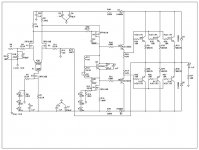
Mr. Pass, I have a couple of simple questions I am hoping you can answer while I wait for more parts. I have included an as built schematic as of this date for your reference.
(1) What area of my circuit is most suspect for lack of current gain?
(2) Is it correctable with the current circuit and semi's?
(3) What might a lack of current gain look like on the scope?
(4) If I lower my driver and output base stoppers by half what issues and or gains might there be?
Thanks, DonS
Attachments
As I recall you were running rather high supply rails, as much
as 70 volts. Figures like that into 4 ohms would mean something
approaching 20 amp peaks. Let's say that's the case, and assign
an arbitrary beta of 50 for the output stage, so we need 400 mA
from the drivers. Most likely 5 mA from the front end will
deliver that, so you're probably not running out of gain.
Unless there's a problem with your load, oscillation is more likely,
but won't know until you see it with a scope.
😎
Nelson Pass said:As I recall you were running rather high supply rails, as much
as 70 volts. Figures like that into 4 ohms would mean something
approaching 20 amp peaks. Let's say that's the case, and assign
an arbitrary beta of 50 for the output stage, so we need 400 mA
from the drivers. Most likely 5 mA from the front end will
deliver that, so you're probably not running out of gain.
Unless there's a problem with your load, oscillation is more likely,
but won't know until you see it with a scope.
😎
OK Mr. Pass, the load was a Vandersteen Model 1. They perform well with a stock Citation 12 and magnitudes better with your A40's (mine are mono blocks, thanks again for the design!) I am sure that I was nowhere near 70V peaks, more like 30V (aah, watching the scope too was I). Based on what you are telling me, then I still have oscillation problems and I did not see them on the scope! OK!
What test load/s should I use and what input signal (types/frequencies) will bring my oscillation problems to the surface most quickly on the scope per say?
I see that you didn't want to answer my question on base stoppers. I know more variables! If the problem is oscillation and if decreasing the value of the base stoppers will raise (possibly a misunderstanding on my part, thinking it will speed up the circuit) the unity gain value/s of the output stage, would this not help spread the "poles" further apart?
Thanks, DonS
Don S said:
If the problem is oscillation and if decreasing the value of the base stoppers will raise the frequency of (possibly a misunderstanding on my part, thinking it will speed up the circuit) the unity gain value/s of the output stage, would this not help spread the "poles" further apart?
Thanks, DonS
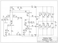
Here is my updated schematic that I believe will help stability, and also current drive limitations of the last schematic posted. I have also increased the FB for an overall gain of 20DB. I did this based on the fact that Mr. Pass stated earlier that he would not run this circuit at more than 20DB of gain. It should help in a number of area's the circuit is lacking in now. I guess if my preamps don't cut it, I will have to build one that will!
Looking at the circuit, can someone suggest how to improve upon the stability?
Note that several small changes have been made and not mentioned above.
Thanks, DonS
Attachments
- Status
- Not open for further replies.
- Home
- Amplifiers
- Pass Labs
- Mosfet Frontend Troubles