Mr. Pass, lowering R17 to 1K0 and R18 to 221R solved the Vbe problem. I can now bias the outputs!!!
However now that I can bias the outputs correctly I have discovered an oscillation issue. Whenever the output stage bias approaches ~35mA total, the amplifier starts to oscillate. I increased the FB by 6dB so the gain is now only 20dB. No change!!! It is also excited by high frequency inputs (which also cause the output bias current to increase), the higher the hZ the lower the input to start it. At 1KhZ the unit doesn't increase current through the emitter resistors and goes to the rails without problems.
Suggestions?
Thanks, DonS
Nelson Pass said:Maybe it's time to see another full schematic.
😎
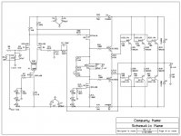
Mr. Pass, here is the latest as built schematic.
Boy is this going to cost me a lot of pistachios!!!!
Thanks, DonS
Attachments
I don't see any obvious thing. Try connecting the output to
the point between R19 and R24 and see if that makes
a difference.
😎
the point between R19 and R24 and see if that makes
a difference.
😎
Nelson Pass said:I don't see any obvious thing. Try connecting the output to
the point between R19 and R24 and see if that makes
a difference.
😎
Mr. Pass, I just tried the above. Maybe, just maybe, the current went up slightly before oscillation. Input was shorted, ect.
Thanks, DonS
Mr. Pass, where should I look to isolate this problem. The Vbe voltage looks pretty stable when the circuit goes into oscillation. Is the large value of C4 (47uF) an issue here?
I am at a loss! The circuit is an opamp with a darlington follower. Pretty standard stuff I think!
Thanks, DonS
I am at a loss! The circuit is an opamp with a darlington follower. Pretty standard stuff I think!
Thanks, DonS
"Boy is this going to cost me a lot of pistachios!!!!" Looks to me like you are saving big time on the power supply components??? I don't see any V+, V- looking connections??? Only earth???
Very green of you Don 😀
Very green of you Don 😀
flg said:"Boy is this going to cost me a lot of pistachios!!!!" Looks to me like you are saving big time on the power supply components??? I don't see any V+, V- looking connections??? Only earth???
Very green of you Don 😀
LOL!! A green oscillator. Is that not like perpetual motion.
The output collectors are supplied ~ +-70VDC. That's it!
Thanks, DonS
Maybe this will help. The 1200 watt transformer has 3, 100W 110V lightbulbs in parallel in front of it, in series with the mains. This is my poorman's variac to prevent the circuit from going poof!
Thanks, DonS
Thanks, DonS
Nelson Pass said:Let's put some capacitance from output rails to the ground of the
output Zobel.
😎
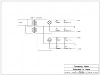
Mr. Pass, I am not sure quite what you mean? I have attached the power supply schematic, which uses 1/8" solid copper bars for supplies and ground. All the power supply caps are bolted directly to these copper bars. The drivers and outputs are also bolted to the bars to get power. The zobel network goes directly across the output terminals, and the negative terminal is the copper bar back to the supply caps and star ground.
Thanks, DonS
Attachments
Mr. Pass, I have discovered that with no FB, the output stage can be biased to any level without oscillation. I tried to take the FB from the node between R19 and R24 instead of the output, no difference. 
Idea's?
Thanks, DonS
Idea's?
Thanks, DonS
Try increasing R21 and R22. After that, think about some
compensation caps for the front end.
😎
compensation caps for the front end.
😎
Nelson Pass said:Try increasing R21 and R22. After that, think about some
compensation caps for the front end.
😎
Mr. Pass, would increasing R21 and R22 to 221R be a good starting point?
Where are we talking for the compensation caps?
Thanks, DonS
Mr. Pass, Increasing R21 and R22 to 200R lowered the bias at which the oscillation started!
Thanks, DonS
Thanks, DonS
Don S said:Mr. Pass, Increasing R21 and R22 to 200R lowered the bias at which the oscillation started!
Thanks, DonS
Mr. Pass, Shorting R21 and R22 raised the bias level at which the oscillation starts.
Thanks, DonS
OK, first try some capacitance Gate to Drain on Q6 and/or
Q4. Also see what happens when you load the Drain of
Q6 with a resistor to ground, starting with 10 Kohm
😎
Q4. Also see what happens when you load the Drain of
Q6 with a resistor to ground, starting with 10 Kohm
😎
Nelson Pass said:OK, first try some capacitance Gate to Drain on Q6 and/or
Q4. Also see what happens when you load the Drain of
Q6 with a resistor to ground, starting with 10 Kohm
😎
Mr. Pass, I was able to load the gate to drain of Q4 with first 47pF, which was a significant improvement. Next I loaded Q4 with 94pF, again another significant improvement. I left it at 94pF and proceeded to step 2 below.
I tried loading Q6 drain to ground, first with 28K, then with 18K, and finally with 4K7. Only 4K7 improved the results, and not by very much.
(R22 and R21 are still 0R0 from the last change!)
Where do I go from here?
Thanks, DonS
At this point, I would put lag (Cgd) compensation on Q6 until
the oscillation stopped. Then I would go back to the circuit
altering values of the caps and resistors until I get improvement,
however small, and I would reiterate the procedure.
Source and Gate resistances on all Mosfets, base resistors on
the BJT drivers, and compensation values (lag on Q6 and feedback
comensation cap are all good targets.
After you fool around with it for a while, you will probably get
pretty close to as much as you can expect.
😎
- Status
- Not open for further replies.
- Home
- Amplifiers
- Pass Labs
- Mosfet Frontend Troubles