Nelson Pass said:OK, so Q4 is conducting 19 mA, and Q6 is conducting 25 mA,
and we have a clear explanation as to why you have a positive
output.
(not clear to me! how can Q6 conduct more than Q4? i don't see the path, what is the math?)
Manwhile, your front end is not doing much to correct this, since
it is not responding to a 1.8V differential.
(with my fb network it will only correct about 3%, correct? then the rest will be the diff pair correcting for the difference of the voltage on the base of Q2 compared to the base of Q1 because a diif pair wants the voltage to be the same on both gates, correct?)
I would start by replacing R3, R4, and Q1 and Q2. Q1 and Q2
should be matched. I would temporarily remove R38 and P1,
connecting the Drain of Q3 to the center point of R3 and R4,
and see what happens.
( i am matching some 610's as we speak, to replace what are in Q1 and Q2 positions. it appears ihave some duds as i am testing with your circuit from the opamps article you wrote. when i disconnect the gate resistor from the device in test the voltage does not change on several devices i have.............. i removed R38 and still could not get the diff to balance across R3 and R4. sounds like i have a dud in the diff now! I will check R3 and R4 and also P1, P38 is out of circuit.)
😎
Thank you again for your help!!!!!
All I have will be community property when I have a working amp. Circuit, PCB layouts, voltages, ect.
Thanks first to Nelson Pass!!! And thanks to everyone else that has been helping. I will update you as I get info. I think I might be on the right path now.
DonS
My two cents worth:
1) You're popping MOSFETs. Whether due to static, burning them up in the circuit, or overheating them during soldering, there's no way to tell. Sit back, take a deep breath, and reevaluate your MOSFET handling procedures. You may need Zeners at the differential Gates to keep outside shocks from roasting the parts in situ.
2) The MOSFETs for the differential should be matched carefully.
3) You will not get predictable current from MOSFET current sources using a string of LEDs to push the Gate. The variance in MOSFET Vgs will kill you. I suggest another CCS topology. With the topology you're chosen, small variances in current will throw the whole circuit out of whack. Yes, yes, yes...I know..."But Grey, I'm using LEDs so the current sources will be quiet. I want the best possible..." Etc. I'm sympathetic, but you need to reduce the variables you're facing. Right now, you're drowning in uncontrolled variables.
4) For the same reason, I'm less than overwhelmed with the idea of R1, R2, and Q6 working against the Q4 CCS. It's pushing the laws of probability to expect that the CCS (which is hard-coded by LEDs 4-6 vs. R16) will somehow, magically, balance perfectly against the quiescent current you'll see through Q6 programmed by R1 and R2. Then throw in the feedback loop back through the differential and...like Twain's pig, it's not that it sings so well, it's that it sings at all. To begin with, see #3 above. Your CCS currents are unpredictable. It's not necessarily a deal-killer, but you're complicating your life, especially if the circuit isn't working. Next, allow me to suggest a pot in place of R1. This will allow you to set the operating point of Q6 regardless of its Vgs. In practice, you'll open the feedback loop, set the pot so that the node at the Drains of Q6 and Q4 settles at 0V (do this a couple of time as the circuit warms up), then close the feedback loop to keep it there. If you're determined to use fixed resistors for the differential loads, then toss the Q6 MOSFET and use a bipolar, which will have a predictable Vbe of around .65V. Recalculate the R1/R2 values accordingly. That will make it a lot easier to do what you're trying to do.
The single most important thing is to get a pot in front of Q6's Gate. Assuming that there are no fried parts, that one thing should allow you to get control of the circuit long enough to beat it into submission.
Grey
Grey, can you look at my post just above your last. I am hoping that you can answer the questions I had after Mr. Pass' quoted response.
I was wandering if you have 2 cents more you could share! Please!
Thanks, DonS
I was wandering if you have 2 cents more you could share! Please!
Thanks, DonS
It is Alive!
I replaced R1 and R2. Q1 and Q2. Testing revealed that Q1 was shorted drain to source! R2 needed to be changed to 39R.
Open loop the DC slowly drifts +- 8V😱
Closed loop it slowly drifts +-500mV😱
Closed loop with a 1K3 resistor to ground it drifts ~ +-275mV😱
Should I be concerned, or will the load of the output stage tame this?😕
Well, I am off to see if the frontend will amplify a signal. Also to see what the signal looks like.
Thanks, DonS
It's ALIVE! It's an amplifier!
A sinewave in looks like a sinewave out!
With 29.8 DB of gain!
1.5V rms in equals 46.5V rms out at 1khertz. No signs of clipping at this level. I ran out of scope with my test setup. I need to pad the scopes input down.
I took a 1khertz sine at 14V PP output and when I raised the signal to 20khertz the gain dropped by ~3DB to 10V PP. 😕
I checked my test equipment and setup, no rolloff there! 50R output impedance of the sinewave generator. No load on the output other than the test equipment.
Can someone tell me why the rolloff is occuring at such a low frequency?
I was expecting the rolloff to be much higher in frequency. Somewhere around 100khertz.
DonS
None of this is particularly surprising. The drift is thermal. It will be less if the circuit is in a case, but it will not cease. You're not using a lot of feedback. If you want less drift, use more feedback, control the temperature, or use parts that are less sensitive to temperature. Or use a "thermal capacitor" such as I described in the Aleph-X thread--a block of metal coupling the input devices, binding them thermally, but not necessarily dissipating a lot of heat.
The bandwidth doesn't surprise me either. The culprit in this case is the capacitance inherent in the MOSFETs. Again, your feedback is modest. If you want wider bandwidth without changing the circuit, you'll need to increase the feedback. If you want to change the circuit, you've got loads of possibilities: Lower capacitance devices, cascode the differential, optimize the rails/bias current, a different topology...etc.
Grey
Re: It's ALIVE! It's an amplifier!
A quick thumbnail calculation says that you would be expecting
a couple poles of rolloff at around 80 KHz or so. On the other
hand, you are operating near open loop - your feedback loop
is asking for almoust 40 dB of gain and getting 30.
Offhand, I would say something is dragging you down a bit.
Keep in mind that with the current circuit you would probably
not want to operate it at greater than 20 dB or so. Try reducing
the 47K to 10K and see what you get.
😎
Don S said:Can someone tell me why the rolloff is occuring at such a low frequency?
A quick thumbnail calculation says that you would be expecting
a couple poles of rolloff at around 80 KHz or so. On the other
hand, you are operating near open loop - your feedback loop
is asking for almoust 40 dB of gain and getting 30.
Offhand, I would say something is dragging you down a bit.
Keep in mind that with the current circuit you would probably
not want to operate it at greater than 20 dB or so. Try reducing
the 47K to 10K and see what you get.
😎
Re: Re: It's ALIVE! It's an amplifier!
Given that I will always have 75V rails (62V right now!) and I need at least 28DB of gain, it looks like I am in a pickle with this circuit. If I increase FB I will have reduced gain, correct? You make mention of bias currents, please clue me in! Is it the diff pair capacitance that is causing this? If this is the case can you suggest some lower capacitance device that I can substitute with 75V rails and this circuit?.
How can I have 28DB of gain with this circuit and still have have a rolloff of -3DB at 100kH. 7+ volts to drive this amp to clipping is not an option. See above.
I will lower R13 to 10k and see what happens! It looks like I will need about 9V to drive it to the rails though, correct?
Even if the response is flat at 20kH it looks like I might need another amp to to provide the voltage swing. All my preamps give up at about 5V.
GRollins said:None of this is particularly surprising. The drift is thermal. It will be less if the circuit is in a case, but it will not cease. You're not using a lot of feedback. If you want less drift, use more feedback, control the temperature, or use parts that are less sensitive to temperature. Or use a "thermal capacitor" such as I described in the Aleph-X thread--a block of metal coupling the input devices, binding them thermally, but not necessarily dissipating a lot of heat.
The bandwidth doesn't surprise me either. The culprit in this case is the capacitance inherent in the MOSFETs. Again, your feedback is modest. If you want wider bandwidth without changing the circuit, you'll need to increase the feedback. If you want to change the circuit, you've got loads of possibilities: Lower capacitance devices, cascode the differential, optimize the rails/bias current, a different topology...etc.
Grey
Given that I will always have 75V rails (62V right now!) and I need at least 28DB of gain, it looks like I am in a pickle with this circuit. If I increase FB I will have reduced gain, correct? You make mention of bias currents, please clue me in! Is it the diff pair capacitance that is causing this? If this is the case can you suggest some lower capacitance device that I can substitute with 75V rails and this circuit?.
Nelson Pass said:
A quick thumbnail calculation says that you would be expecting
a couple poles of rolloff at around 80 KHz or so. On the other
hand, you are operating near open loop - your feedback loop
is asking for almoust 40 dB of gain and getting 30.
Offhand, I would say something is dragging you down a bit.
Keep in mind that with the current circuit you would probably
not want to operate it at greater than 20 dB or so. Try reducing
the 47K to 10K and see what you get.
😎
How can I have 28DB of gain with this circuit and still have have a rolloff of -3DB at 100kH. 7+ volts to drive this amp to clipping is not an option. See above.
I will lower R13 to 10k and see what happens! It looks like I will need about 9V to drive it to the rails though, correct?
Even if the response is flat at 20kH it looks like I might need another amp to to provide the voltage swing. All my preamps give up at about 5V.
You can increase the open loop gain by reducing the value
of the Source to Source resistors on the input differential
pair. This will give you some more open loop gain to play
with.
Also, start looking at the capacitances in the circuit. Try removing
the feedback capacitor and see what happens.
😎
of the Source to Source resistors on the input differential
pair. This will give you some more open loop gain to play
with.
Also, start looking at the capacitances in the circuit. Try removing
the feedback capacitor and see what happens.
😎
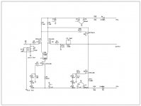
Update!
I now have -3dB @100kH
27dB of gain
DC offset of +-70mV (conservatively) all though it still floats alot and is a pia to adjust.
The adjusted circuit is attached below.
This is my path to improvement.
R38 was out of circuit, I put it back in. Little improvment in any areas.
Changed R13 to 39k0, improved bandwidth, slightly lower offset variance.
Changed R13 to 33K0, now I was only down 4dB @ 100kH, again slightly lower offset, but still nothing to write home about.
Changed R3 and R4 to 0R, now we're talking! Down 3dB @ 100K now! Big side benefit was the DC offset was greatly improved with this change. (See above for the specs.)
My next change will be to swap out P1 for a 100R pot, and R38 to ~ 22R. Then I should have a good stable DC offset with easy control! My bandwidth should improve slightly also!
I will keep you informed!
Can someone tell me the openloop gain of this circuit, and how to calculate this?
Thanks all, DonS
Attachments
Well here I am with a working frontend. 🙂
I have increased the FB and seen an improvement in frequency response to -1.9dB @ 100kH. (More than I need.)
Gain is 25dB. (I will shoot for 26dB and be happy!)
DC drift is still a problem! It is still no better than +-60mV🙁 (That is if I don't blow on the board.) I am afraid if the A/C kicks on my woofer's will shoot through the wall! 😱
Here is my list of fixes.
Couple Q1 and Q2 together thermally.
Lower P1 and R38 as described in my last post.
Pray for divine guidance! LOL!!!!
Seriously without adding more Fb to the circuit, what else can I do.
Will having the same voltage reference for both current sources help? Or running more current through them help?
Will things improve when I connect the FB to the output stage because of the low impedance?
I suppose I could put a cap between R12 and ground, but I think that might be a last resort. I also don't know how to calculate the value of that cap if I do. ( To give a LF rolloff of -3dB at ~1hZ )
I am just guessing and need some help!
DonS
Will increasing the current through the diff pair increase their transconductance? Will increasing their gain help with the DC drift?
Inquiring minds want to know!
And these are the days of the opamp. LOL!
Sorry, I am in a manic mood right now. 3 days awake watching the DC drift on O-scope and meter, no commercials!
Please help.
DonS
Inquiring minds want to know!
And these are the days of the opamp. LOL!
Sorry, I am in a manic mood right now. 3 days awake watching the DC drift on O-scope and meter, no commercials!
Please help.
DonS
Will increasing the current through the diff pair increase their transconductance? Will increasing their gain help with the DC drift?
I believe the correct answer here is no--I tried it with the mini-a--no noticeable improvements.
Sorry, I am in a manic mood right now. 3 days awake watching the DC drift on O-scope and meter, no commercials!
Please help
+-60mV dc is teeny. Try it with the output stage. My mini-a with the incorrectly sized resistor has 300mV dC on one channel. I've been listening to it every night. (ok, so the speaks have 4 woofers is SP, I guess I wouldn't try it with a $500 Lowther driver).
Having the dc change when you blow on it is normal. It will be much more stable once in the amp.
JJ
jupiterjune said:
Ok, heres your help--Hook it up to some speakers and LISTEN TO SOME MUSIC!!! (sorry for the yelling, but it sounded like you might be dozing off.)
🙂
JJ
Maybe I will! I am just not into the Sinewaves though!
JJ, I still have not hooked up the output stage. I am still very concerned with the DC offset drift. (Read terrified!)
I don't have a variac, so I use the 100W bulb in series trick. Very unnerving when you have a 1200W transformer. I have had 2 minor welding accidents just working on the frontend. 😱
DonS
I don't have a variac, so I use the 100W bulb in series trick. Very unnerving when you have a 1200W transformer. I have had 2 minor welding accidents just working on the frontend. 😱
DonS
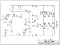
Output Stage Questions
I was planning to use the A40 bias FB scheme. This is R23 and D1 in the circuit. My questions are,
Will this method work with a low bias setting?
(If my math is correct 56mA's per device will dissipate 25W of heat into the sinks. 0.056mA X 0R235 = 13mV)
Will this work better with Q5 mounted on the output heatsink, or should I just mount Q5 on the output sink and forget about R23, D1?
(Didn't want to mount on heatsink because of wiring length. About 6")
BTW the value of R23 was just a WAG on my part!
Mr. Pass, Grey. Idea's?
I have included the updated full schematic below.
Thanks, DonS
Attachments
Re: Output Stage Questions
No. It really only works for Class A.
😎
Don S said:I was planning to use the A40 bias FB scheme. This is R23 and D1 in the circuit. My questions are,
Will this method work with a low bias setting?
No. It really only works for Class A.
😎
Mr. Pass, If I just mount Q5 next to the outputs, I should just be happy? Yes?
Does the VAS stage have enough drive for Q7,8?
Thanks, DonS
Does the VAS stage have enough drive for Q7,8?
Thanks, DonS
A simple Vbe multiplier like you have without R23 and D1
should be fine.
Does the Vas have enough current? Depends. I see that you
have very high rails, so are you planning on delivering +/- 20 amps
into the load?
😎
should be fine.
Does the Vas have enough current? Depends. I see that you
have very high rails, so are you planning on delivering +/- 20 amps
into the load?
😎
- Status
- Not open for further replies.
- Home
- Amplifiers
- Pass Labs
- Mosfet Frontend Troubles