TIP36 ---> MJE5731AG qty=1 price USD 1.36 at DigiKey
BD139 ---> ZTX458 qty=1 price USD 0.65 at DigiKey
_
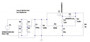
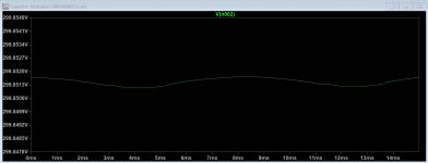
I also did a simulation of the original circuit. See attached startup and filtering result. Very impressive except the significantly lower output voltage, 299.851V vs Mark's 307.279V.
Interestingly, if I take off the 220K R3, the performance deteriorates.
I could not simulate ST901 because I could not find a Spice model for it. I did a simulation using MJE5742 power Darlington. It needs a lot of base current and did not work well.
Attachments

I am sorry to tell you that you have misunderstood the subtleties of Rod Elliott's circuit fairly dramatically. To name one example, why does Elliott have a "12K" resistor in the attachment to post #11, whereas your schematic uses "infinity" instead?
Mark is trying to tell you that Rod feeds the base or gate of the pass device with a voltage divider so that there is a voltage drop across the pass device.
Rod's article says that a voltage drop of a few volts across the pass device improves its performance.
Steve
Rod's article says that a voltage drop of a few volts across the pass device improves its performance.
Steve
I am sorry to tell you that you have misunderstood the subtleties of Rod Elliott's circuit fairly dramatically. To name one example, why does Elliott have a "12K" resistor in the attachment to post #11, whereas your schematic uses "infinity" instead?
I understood his explanation. However, I want to have the slow start function as the original circuit published by Menno does. If I replace the 12K resistor with a 1 meg one, I could not adjust the 220 ohm resistor to get the slow start function and the low voltage drop that I want.
I was a bit surprised that LTspice simulation actually works well for the bipolar circuit. I worried that the 560K ohm resistor might not supply enough base current to ZTX458. The simulation result indicated around 4V drop across the circuit. This might be a concern for a class AB amp. However, the power supply feeds a Class A single ended amp with likely CCS for output tube cathodes. I don't expect much fluctuation in current demand.
There might be some trick that can make the bipolar circuit to work as I want or I indeed misunderstood Rod. However, if the bipolar circuit gets much more complicated, the MOSFET circuit will be preferred. It has low parts count and the insulated device can be mounted directly on the case without a PC board. As I plan to build the amp point to point, that will definitely be a plus.
I want to have the slow start function..
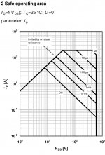
For a slow start you need to take a look at the safe operating area for the pass device. Here is the graph for the MJE573x series:

Notice how low the safe collector amperage is for a high collector-emitter DC voltage.
This thread has some good info: HV bench power supply design

Actually, it turns out the SOA is unlikely to be an issue with the specific tube amp I plan to build. The output tubes of the amp will start to draw current when they heat up (around 23 seconds after turned on) and ramp to full current in 5 more seconds.
If I move the 220K bleed resistor from before the capacitor multiplier to after it as a load, the voltages of the circuit will be close to the operating point by the time the amp starts to draw high current. At that point, the voltage drop across the MOSFET is less than 20V. It can handle the 150 mA load easily. Before that point, the current draw will be less than 2 mA.
However, the MOSFET may blow if there is a brief power interruption. When the power resumes, the power tubes are still hot and can draw full current. On the other hand, since the circuit will ramp the voltage back up slowly, the amount of current draw should be less than the design target. Any way, a bit more safety margin for the device will be desirable.
I am using a 2N5551 cap multiplier on 2 6922's providing a B+ of 135v from a 148v voltage tripler
the 60hz and 120 hz ripple is below the noise floor of the tubes.
there is a 2.5 v p-p ripple before the transistor.
the 60hz and 120 hz ripple is below the noise floor of the tubes.
there is a 2.5 v p-p ripple before the transistor.
Can i jedi mind trick the OP into a real mosfet for this kind of job?
IXTH15N50L2
If you really really want to use a BJT, TIP50 was the highest SOA device i could find, at 50mA 400V SOA if memory serves me correctly.
IXTH15N50L2
If you really really want to use a BJT, TIP50 was the highest SOA device i could find, at 50mA 400V SOA if memory serves me correctly.
- Home
- Amplifiers
- Tubes / Valves
- MOSFET for capacitor multiplier