Mosfet follower driver oscillation
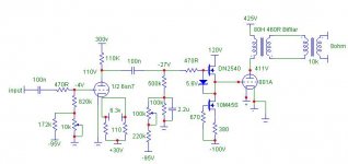
I've been using a DN2540 follower as a buffer/driver for an 801A2 amp. Recently, I wanted to see if replacing the source resistor with a CCS would make a difference. Not sure if I hear a difference yet, but I have observed that if I leave the input to the amp open, the bias on the output tube starts to go up quickly. Doesn't happen with the amp connected to a normal source or with the input shorted. I suspect that the DN2540/10m45S combo is oscillating when given a chance. I have a 670 Ohm stopper resistor on the gate of the 10m45. Maybe a higher value, or should I look at something else? Maybe the high value for the gate resistor from the 2540 to the bias supply is an issue? Or could the protection zener be a problem? Suggestions welcomed.
Sheldon
Attachments
Also, I would move output tube bias trimpot to a ground like it is done for your 1'st tube: noise in it when adjusting will cause peaks of current in the output tube.
Fuling said:The zener should be connected "outside" the gate stopper resistor.
Thanks, that makes sense. I'll give it a try.
Wavebourn said:Also, I would move output tube bias trimpot to a ground like it is done for your 1'st tube: noise in it when adjusting will cause peaks of current in the output tube.
Yes, that does seem the better way. Thanks.
Sheldon
One other thing that sometimes helps when all else fails is a small resistor right at the drain - 10 ohms ought to be enough. (De Q the surrounding wiring at vhf..)
kevinkr said:One other thing that sometimes helps when all else fails is a small resistor right at the drain - 10 ohms ought to be enough. (De Q the surrounding wiring at vhf..)
Thanks Kevin, I assume you mean on the drain of the follower device, as the connection between follower and CCS is only a couple of cm. Though, I guess it couldn't really hurt there either.
Sheldon
I found the problem. Turns out that I had some metal debris that was causing some conduction from the drain of the 10m45 to ground. Cleaned that up and problem gone. I went ahead and made the circuit changes (drain stoppers, including gate stopper behind the safety zener, and moved the trim pot to the ground leg), just make the engineering more solid.
sheldon
sheldon
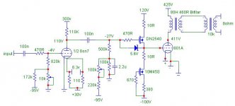
Hmm, turns out the solder issue did not cure everything. These things seem to want to oscillate. I made changes as per the following and had problems when I tried to use a CCS on the driver tube. Thought I might have goosed something a little too hard, and cooked one of the IXYS devices. I had to replace one, so I just replaced both with DN2540, with the appropriate changes to get the correct current. All tests out fine on the bench. But when I power up the output tubes, things go south and the bias goes away. Here's the schematic with the IXYS shown. Any ideas, before I just go back to a resistor load on the source follower?
Sheldon
Sheldon
Attachments
ferrite beads
Hi,
I previously encountered oscillation in many of my designs (very high bandwidth) but cured most all of them placing small ferrite beads (I guess they are normally used to filter out high frequency noise) on the transistor's pins.
In my opinion is also made the circuit sound better - somewhat quieter and less diffuse.
Regards,
Jesper
Sheldon said:Hmm, turns out the solder issue did not cure everything. These things seem to want to oscillate. I made changes as per the following and had problems when I tried to use a CCS on the driver tube. Thought I might have goosed something a little too hard, and cooked one of the IXYS devices. I had to replace one, so I just replaced both with DN2540, with the appropriate changes to get the correct current. All tests out fine on the bench. But when I power up the output tubes, things go south and the bias goes away. Here's the schematic with the IXYS shown. Any ideas, before I just go back to a resistor load on the source follower?
Sheldon
Ground loop may be?
Wavebourn said:
Ground loop may be?
I'll look closely, but I have no problem when the source is loaded with a 10K resistor instead of the CCS.
Tony said:hi sheldon, could it be you got your zener diode backwards? i would use them back to back...😀
The DN2540 is a depletion mode device. The gate is at lower potential than the source.
Sheldon
One thing I found out accidentally is that DN2540 will smoke if you don't power it up in just the right order. For a follower like this, the depletion mode doesn't carry much advantage, so you might think about switching to a more prosaic enhancement mode device.
Sheldon said:
The DN2540 is a depletion mode device. The gate is at lower potential than the source.
Sheldon
But, it can be operated as an enhanced device > gate to source positive. Iguess something like 2 zeners to protect this FET ?
Using a CCS as the grid 'leak' resistor for the 801A2 might be the reason for bias runaway. Try connecting a 100k resistor in parallel with the CCS, i.e. from the 801A2 grid to ground. This shouldn't materially affect the operation of the CCS but it will satisfy the maximum grid-cathode resistance requirement of the 8012A under fixed bias conditions. IF you're using a cathode bias resistor, a 470k grid 'leak' resistor will do.
Sheldon said:
I'll look closely, but I have no problem when the source is loaded with a 10K resistor instead of the CCS.
Different capacitances cause different currents on highs through ground loops.
Thanks for the suggestions. I'll file them for future use (maybe even tomorrow). Wavebourn was onto something - an extra ground issue. The immediate problem seems to have been a partial short between one of the FET's and heat sink. No conduction when I assembled it, but maybe with heat expansion, a little burr dug its way through. I replaced a cooked FET, lapped them all along with the heat sink. Seems fine now.
I'll take a break and listen to music, then see if I can implement a plate CCS on the driver tube.
Sheldon
I'll take a break and listen to music, then see if I can implement a plate CCS on the driver tube.
Sheldon
SY said:One thing I found out accidentally is that DN2540 will smoke if you don't power it up in just the right order. For a follower like this, the depletion mode doesn't carry much advantage, so you might think about switching to a more prosaic enhancement mode device.
Interesting. In this case, the bias voltages are all derived from the same supply, so come up quickly and essentially concurrently. The bias will lag the rails just a little because of the extra RC sections.
If if problem becomes a recurring issue, I guess I could use a regular Mosfet as the follower and a DN2540 for the current sink.
Sheldon
You are right SY about these being touchy. I've lost a few now when I play with the amp under power. If everything is properly wired, I don't seem to have any issues. I've got the follower loaded with a resistor now, and it's fine limited swing. But I get significantly less distortion with the current source load when I try to swing more voltage, so I'm going to switch back. Interestingly, if I load the 6SN7 with a cascoded DN2540, the distortion increases slightly over the resistor load, even at larger voltage swing.
Sheldon
Sheldon
- Status
- Not open for further replies.
- Home
- Amplifiers
- Tubes / Valves
- MOSFET follower driver oscillation