The following subject has probably been developed before, but I could not find it in the records.
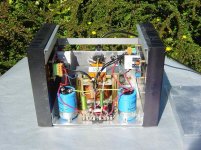
My son has built a Single ended ( yes, single ended ) Mosfet amp, using a heavy duty OPT.
Based on the theory that Mosfets behave very closely like valves, we fitted, as a trial, two different types of OPTs, that had been previously used with an amp fitted two parallel 6C33C-Bs (estimated internal resistance = 50 ohms ).
The first OPT had an impedance of 300 ohms, the second 800 ohms.
In spite of the fact that the mosfet ( an IRFPG30 of the International Rectifiers C° - used with B+ = 130 V at 500 mA current) is stated to have a much lower internal resistance, the best results, in terms of sound ( at circa 20 W output ), were obtained with the higher Z ouput transformer.
This suggests a peculiar dynamic behaviour of the Mosfets, compared to valves.
I am sorry, but my knowledge in the solid state field is quite poor, so I am addressing to you, to eventually find someone with a specific experience and knowledge in this matter.
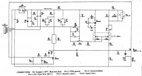
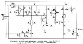
For your information the tests are going on and the schematics of the amplifier are being modified for better general results.
The final layout should be ready within a couple of months.
If I succeed to reduce the size of the bench amp to an acceptable ( by DIYaudio) volume of bytes (102 k ), I will send it asap.
Ari.
My son has built a Single ended ( yes, single ended ) Mosfet amp, using a heavy duty OPT.
Based on the theory that Mosfets behave very closely like valves, we fitted, as a trial, two different types of OPTs, that had been previously used with an amp fitted two parallel 6C33C-Bs (estimated internal resistance = 50 ohms ).
The first OPT had an impedance of 300 ohms, the second 800 ohms.
In spite of the fact that the mosfet ( an IRFPG30 of the International Rectifiers C° - used with B+ = 130 V at 500 mA current) is stated to have a much lower internal resistance, the best results, in terms of sound ( at circa 20 W output ), were obtained with the higher Z ouput transformer.
This suggests a peculiar dynamic behaviour of the Mosfets, compared to valves.
I am sorry, but my knowledge in the solid state field is quite poor, so I am addressing to you, to eventually find someone with a specific experience and knowledge in this matter.
For your information the tests are going on and the schematics of the amplifier are being modified for better general results.
The final layout should be ready within a couple of months.
If I succeed to reduce the size of the bench amp to an acceptable ( by DIYaudio) volume of bytes (102 k ), I will send it asap.
Ari.
Most MOSFETs behave more like pentodes - with very high output impedance and that is perhaps why a higher impedance OPT works better - it provides for higher gain and lower input voltage for the same output - i.e. lower distortion.
The main problem with MOSFETs comparing to valves - FETs got much higher capacitances and these change quite heavily with voltage. In this respect the driver for a MOSFET stage should have low output impedance for it to be able to counteract these effects (including Miller capacitance).
Second problem is that parameters of a MOSFET do considerably change with temperature and so in a zero feedback amp additional thermal distortions would occur.
Alex
Dear Alex,
Thanks for your explanations.
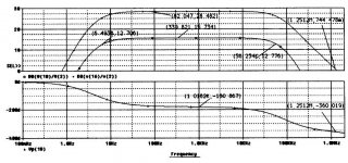
The two problems you stated are under control ( temperature and frequency). In fact, the range extends beyond 70 kHz.
But I do not understand the comparison with the penthodes.
These have notoriously a high internal resistance, whereas the Mosfets are supposed to have a very low one ( few ohms or less).
Ari.
Thanks for your explanations.
The two problems you stated are under control ( temperature and frequency). In fact, the range extends beyond 70 kHz.
But I do not understand the comparison with the penthodes.
These have notoriously a high internal resistance, whereas the Mosfets are supposed to have a very low one ( few ohms or less).
Ari.
ari polisois said:
But I do not understand the comparison with the penthodes.
These have notoriously a high internal resistance, whereas the Mosfets are supposed to have a very low one ( few ohms or less).
Hi Ari
The Mosfets have a very high output impedance , their Drain is a NEAR perfect current source.
Cheers
MOSFETs are seen as low resistance because, switched on, they are. In the linear range, they present a very high Zo and probably sound bad as a result. You need degeneration (NFB of some sort or another) to reduce the Zo to compare to a triode.
MOSFETs saturate in the 0.1 to 10V range while tubes saturate in the 10 to 500V (and greater for larger transmitter types) range. A typical high voltage (and high current and power, mind you) MOSFET might register 5 ohms ON resistance, while a sweep tube such as 6KD6 shows about 40 ohms ON resistance (at great cost to the screen current unless operated carefully, mind you).
Tim
Dear friends,
Apart from other considerations, do you mean that I should use a high impedance OPT ?
The higher the better or is there a rule, like with valves ?
Ari.
Apart from other considerations, do you mean that I should use a high impedance OPT ?
The higher the better or is there a rule, like with valves ?
Ari.
You can draw a load line for MOSFETs the same way as for valves. Another thing about the differences in the transformer loads could be the primary inductance; if the high impedence transformer has a higher inductance, then it will have a more extended bass response. This will make it sound better. 😀
ari polisois said:Dear friends,
Apart from other considerations, do you mean that I should use a high impedance OPT ?
The higher the better or is there a rule, like with valves ?
Dear Ari
As the mosfet have a high transconductance (more than 1 S = 1 amp/volt ) and can output many amps of current , you can't use a high impedance output transformer , because that way ,you will have a very high voltage output excursion at the mosfet drain..
Imagine a mosfet outputting 1 Amp in a 1k Ohm load it will make a voltage swing of 1000 Volts

Salut!
What are the rail voltages? I'm curious why you would use an OPT with a mosfet because they work under lower voltages and higher currents than tubes. But I'm far from being an expert...
Thanks, I am beginning to see the light ( although some explanations are - in my head ) conflicting.
Dear Evaas - I will try to reduce the file size ( schematics and photo) to an acceptable value.
If I do not succeed, can I send it to you direct by e-mail ?
Dear Evaas - I will try to reduce the file size ( schematics and photo) to an acceptable value.
If I do not succeed, can I send it to you direct by e-mail ?
Think of it this way. Output impedance is a response and can be controlled electronically; it has absolutely nothing to do with the actual capabilities of an amplifier.
A solid state amp of 10W might have a damping factor (Rl / Zo) of 10 or more, while a ZNFB pentode amp of 100W might run 0.2 (i.e., Zo = 40 ohms).
Tim
A solid state amp of 10W might have a damping factor (Rl / Zo) of 10 or more, while a ZNFB pentode amp of 100W might run 0.2 (i.e., Zo = 40 ohms).
Tim

- Status
- Not open for further replies.
- Home
- Amplifiers
- Tubes / Valves
- Mosfet differences with valves