HI guys,
Can you please explain to me why some mosfets make for a better constant current source than others?
I was trying to add a constant current source to a power amplifier driver stage and I found that the problems in the simulation resided in the current source that behaved very poorly.
I have made a separate simulation only with the current source to understand what I’ve done wrong.
Below you’ll see two examples, one that uses IRF640 and behaves as expected and a second one that use IRF720 and behaves poorly.
THESE ARE SIMULATIONS, NOT MEASUREMENTS!
I did not build this constant current source yet(but i'm planing to...).
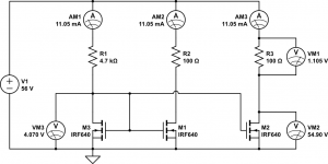
IRF640 DC currents

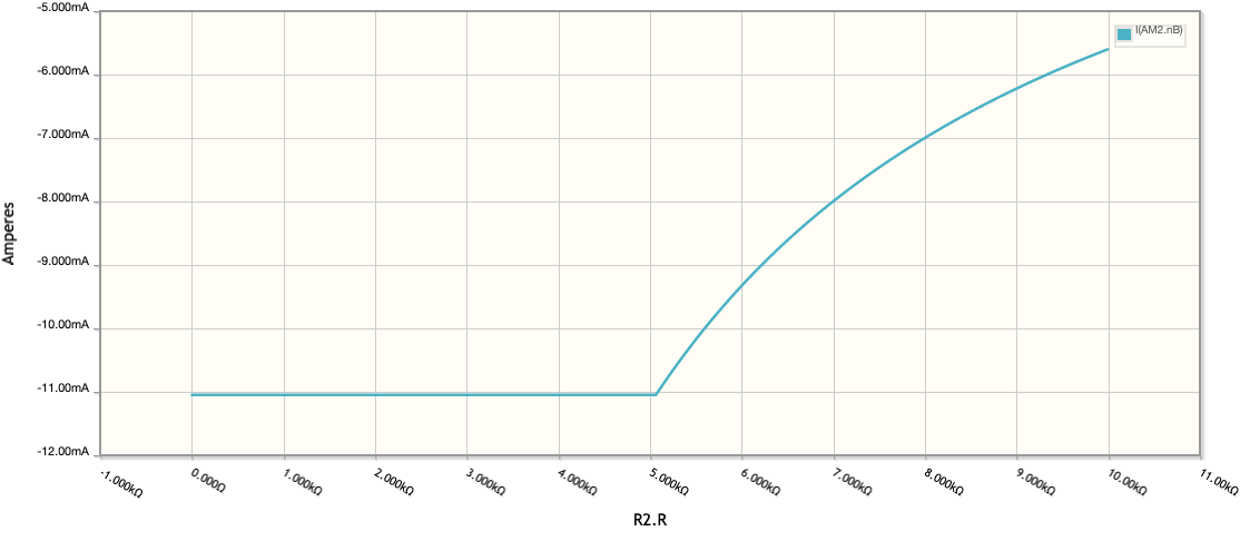
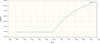
IRF640 DC SWEEP
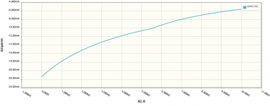
Evolution of I (AM2) when R2 is changing from 1 to 10k
And now the problematic one
IRF720 DC Currents (notice that they are not equal)

IRF720 DC SWEEP
Evolution of I (AM2) when R2 is changing from 1 to 10k
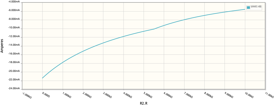
Notice that the current is not constant at all.
Most of the other transistor models that i have tried yield results between those two, though closer to the IRF640.
Why is that?
Can you please explain to me why some mosfets make for a better constant current source than others?
I was trying to add a constant current source to a power amplifier driver stage and I found that the problems in the simulation resided in the current source that behaved very poorly.
I have made a separate simulation only with the current source to understand what I’ve done wrong.
Below you’ll see two examples, one that uses IRF640 and behaves as expected and a second one that use IRF720 and behaves poorly.
THESE ARE SIMULATIONS, NOT MEASUREMENTS!
I did not build this constant current source yet(but i'm planing to...).
IRF640 DC currents
IRF640 DC SWEEP
Evolution of I (AM2) when R2 is changing from 1 to 10k
And now the problematic one
IRF720 DC Currents (notice that they are not equal)
IRF720 DC SWEEP
Evolution of I (AM2) when R2 is changing from 1 to 10k
Notice that the current is not constant at all.
Most of the other transistor models that i have tried yield results between those two, though closer to the IRF640.
Why is that?
Attachments

Last edited:
not sure what you're trying to demonstrate yet.
are you sure you want M3 drains connected to M3 gates?
mlloyd1
are you sure you want M3 drains connected to M3 gates?
mlloyd1
not sure what you're trying to demonstrate yet.
are you sure you want M3 drains connected to M3 gates?
mlloyd1
the principle is explained here
First off in the real world you need source resistors b/c no two discrete MOSFETs are equal and the currents will vary wildly without source resistance. It's a good idea to have a resistance that gives a source voltage drop about equal to the gate-source threshold voltage at given current, so roughly 3.5V at the desired current. If you aim for 11mA you want a resistance of about 3.5/0.011=318ohm, so try a 330ohm value for starters. This will lower your headroom a little, but irons out any differences in the MOSFETs, they no longer need to be matched.
Also, the output current sink in the mirror will always have slightly higher current than the reference mirror FET since it has higher drain voltage. The drains are not ideal and will as the voltage increases the drain current will too even if the gates are held constant.
Also, the output current sink in the mirror will always have slightly higher current than the reference mirror FET since it has higher drain voltage. The drains are not ideal and will as the voltage increases the drain current will too even if the gates are held constant.
Oh btw, those power FETs are not great for CCS since they are rather big and have high parasitic capacitances. At least if you want good CCS over a wide bandwidth. They will work fine, but IRF610 and IRF710 are better, at least at the currents shown.
Hi Zak, your CCS circuit is one of those that work in theory but just don't work in practice.
Here are some problems:
- Matching (will affect both circuits - IRF640 and IRF730): VT in discrete MOSFETs match really poorly, therefore, VGS at a given ID will match poorly. This will give you gross errors in your mirror. You will not see this in simulation though. FIX: Use degeneration resistors in the source of the MOSFETS like our USMC friend SemperFi suggests.
- Output impedance: The output impedance of MOSFETs is actually terrible since they have awful Early voltages (VA). As a result you get a lot of variation in ID vs. VDS. My guess is that what you see in the 640 case (yes the 640) is not even real. Looks too good, which may hint the VA is not modeled properly. FIX: Cascode the current sources.
All in all, if you want my opinion, MOSFETs are just not the way to go for a CCS. Use BJTs. They match better, have lower output capacitance, and better output impedance. For your voltages, a current mirror with a 2SC3503 will do just fine. If base current bugs you, there are several tricks to fix it, so no need to even stress about it.
I would throw out the mosfet CCS and use bipolar transistors.
The gate turn on voltages vary more on mosfets.
Try a couple of MPSA42 or MPSA92.
The gate turn on voltages vary more on mosfets.
Try a couple of MPSA42 or MPSA92.
Thanks for your comments guys! I'll take them in consideration when implementing the prototype. But these are simulated results...the data does not came from real measurements but from a spice simulator.
So my question was a rather theoretical one(in practice i'll use your suggestions).
why some transistor simulate a constant current source better than the others? these two examples are the extremes, most of the other transistors models that I've simulated are somewhat between those, though closer to IRF640.
First off in the real world you need source resistors b/c no two discrete MOSFETs are equal and the currents will vary wildly without source resistance. It's a good idea to have a resistance that gives a source voltage drop about equal to the gate-source threshold voltage at given current, so roughly 3.5V at the desired current. If you aim for 11mA you want a resistance of about 3.5/0.011=318ohm, so try a 330ohm value for starters. This will lower your headroom a little, but irons out any differences in the MOSFETs, they no longer need to be matched.
Also, the output current sink in the mirror will always have slightly higher current than the reference mirror FET since it has higher drain voltage. The drains are not ideal and will as the voltage increases the drain current will too even if the gates are held constant.
Thanks for your suggestion!
So far, my method to determine the value of the source resistor value was to multiply the RDS(on) or 1/gfs (Forward Transconductance ) by a factor of 10. in this case 1X10=10 ohm.
Your suggestion is for 330 ohm. 33 X bigger than that, so they are not close.
did i get this wrong?? do you have any practical experience with this? (cause i don't - i just learn it from internet)
Never trust models! Never fully trust simulations!
Models are usually more ideal than real, and two of teh same models are always the same, in real they never are.
RdsON is not even concidered when operating FETs linear. The Vgs value is from the Vbe rule of thumb. Vgs may be a little high, but I have many experiences where having the source resistors as large as practical is good for matching and drift. The only practical issue is if the voltage over the source resistor is so large that you dont have enough dynamic headroom ('compliance' I think it is called when speaking of CCS).
regarding source resistors, i was also thinking to use a cheap transistor (IRF710-IRF730 etc) and buy 25 pieces . match them and forget the source resistor. is this feasible?
regarding source resistors, i was also thinking to use a cheap transistor (IRF710-IRF730 etc) and buy 25 pieces . match them and forget the source resistor. is this feasible?
No.
But by all means, try and learn, best thing you can do. Worst thing you can do is sit on this forum all day and never build anything, no time for both...
No.
But by all means, try and learn, best thing you can do. Worst thing you can do is sit on this forum all day and never build anything, no time for both...
don't worry, i'm a builder!😀
I have a working prototype of the amplifier for more than two weeks now. I just want to improve the VAS stage, and one of the improvements(also a suggestion from this forum) was to add a constant current source. I've looked for info on internet, I've move on to simulation and encounter problems.
Sorry for asking so many questions, is just that there are really nice persons on this forum and advises from more experience guys help me get expected results much faster and cheaper that making working prototypes every time i have an idea.
thank you all for taking time to respond!
Even if you find really well matched sets of transistors, you will find the temp drift excessive without source/emitter degen.
If you at least have some degen, even if to have o nice place to measure current, the drift will be less, and probably settle at some ok value. But just a small flow of air may be enough to have the current vary a little. So its up to you how much drift to tolerate, if drift and offset in the VAS does effect the bias and offset further down, you want the CCS to be as accurate and stable as possible. If it does drift with temp, it should drift so it cancels thermal runaway.
If you at least have some degen, even if to have o nice place to measure current, the drift will be less, and probably settle at some ok value. But just a small flow of air may be enough to have the current vary a little. So its up to you how much drift to tolerate, if drift and offset in the VAS does effect the bias and offset further down, you want the CCS to be as accurate and stable as possible. If it does drift with temp, it should drift so it cancels thermal runaway.
Agree on the preference on BJTs.
But here again, use degeneration equal to one Vbe, 0.7V - ish.
That is way too much. Degeneration is not a multiple of VBE but a multiple of VT = KT/q. The "I don't want too think about it" value is 260mV which is about 10 VTs. Then you dial from there. If headroom is a big deal, you can go down to 150mV. If output impedance is a big deal, then you can go up or better yet, cascode.
Thanks for tip I will test that. I learned having one Vbe is the rule of thumb. Not thinking rules are even better. But since T varies depending means I will end up thinking... but I will try it.
Thanks for tip I will test that. I learned having one Vbe is the rule of thumb. Not thinking rules are even better. But since T varies depending means I will end up thinking... but I will try it.
In IC design (my background), current sources are usually biased PTAT, so that the 260mV tracks temperature. In discrete design, PTAT current sources are impractical, so going with the higher value is usually a good idea (260mV). This way even at higher temperatures, when 260mV represents less than 10 VTs, things are still ok.
As you say, give it a shot.
i think i found the answer i was looking for.
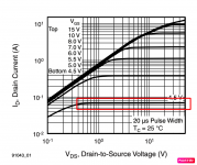
The cause IRF730 behaves/simultates so bad as a constant current source can be found in the Typical Output Characteristics graph, (IDrain vs VDrainSource).
in order to keep the current constant over a wide range of VDS the mosfet must be in saturation and the ID line must be horizontal. If the line has a slope, the current will vary by the amount predicted by the slope over that voltage range.
I could verify this by simulations.
I was interested in 20-50 mA ID curves from 10 to 40 VDS.
of course , in practice i'll put some gate resistors as all of you suggested.
Thank you all for your comments!
p.s.
first capture is for IRF730 and the second one from IRF640 datasheet
Attachments

Last edited:
That will do it... go BJT though 🙂.
i think i found the answer i was looking for.
The cause IRF730 behaves/simultates so bad as a constant current source can be found in the Typical Output Characteristics graph, (IDrain vs VDrainSource).
in order to keep the current constant over a wide range of VDS the mosfet must be in saturation and the ID line must be horizontal. If the line has a slope, the current will vary by the amount predicted by the slope over that voltage range.
I could verify this by simulations.
I was interested in 20-50 mA ID curves from 10 to 40 VDS.
of course , in practice i'll put some gate resistors as all of you suggested.
Thank you all for your comments!
p.s.
first capture is for IRF730 and the second one from IRF640 datasheet
- Home
- Amplifiers
- Solid State
- MOSFET Constant Current Source Question