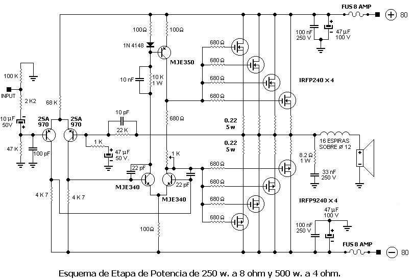
Hello, you would like to know if this circuit is correct, because I tested it on MULTSIM and it did not work. Can you help me?
We don't know what your models or sim files were to even suggest what your problem might be. You would need to simulate in LTspice and post the asc. file to enable a proper analysis but you could post an image of the Multisim screen display of the schematic and someone might be able to spot your problem if it's evident there.
Significant problem is that there is no thermal control for the bias of the output stage.
You can use a 680R+pot for the bias generator on a lateral mosfet, but not for hexfets.
I would suggest you use a small hexfet like a IRF710 to form the bias generator.
Then a few hours with LTSpice running through the simulations to be sure, then build and test it. This might give you more ideas about compensation too; I suspect it might more than 22pF caps.
HD
The diagram seems to be one published in Foros de Electrónica. I think this diagram is very similar to
To several used for mosfets amplifier.
To several used for mosfets amplifier.
It looks like a very poor adaptation of a Lateral Mosfet amplifier circuit.
As shown bias is not enough by any means, you will have *horrible* distortion, and if you increase it to avoid crossover then amp will thermally overrun and burn.
And compensation was probably good for the original one, but this one may very well be unusably unstable.
In a nutshell, it is a mess.
Search for a "real" amplifier circuit, with proper background.
The front end is from a very old lateral mosfet circuit from a Hitachi datasheet for lateral mosfets.
As you are now using vertical mosfets you need a proper Vbe multiplier circuit.
You might need to increase the current through the Vbe multiplier for that many output mosfets.
As you are now using vertical mosfets you need a proper Vbe multiplier circuit.
You might need to increase the current through the Vbe multiplier for that many output mosfets.
1. If you have simulated it, then you can probe the simulation to determine what is not right.
2. A very similar circuit is included in the latest (free) LTC spice down load, a "100Watt" amp.
3. Real problems with this amp include
-slew limit due to limited VAS current driving many gate capacitance
-VAS voltage limits prevent output from getting anywhere near the rails.
-differential VAS only complicates the circuit and does not provide any performance benefit.
It looks like a very poor adaptation of a Lateral Mosfet amplifier circuit.
As shown bias is not enough by any means, you will have *horrible* distortion, and if you increase it to avoid crossover then amp will thermally overrun and burn.
And compensation was probably good for the original one, but this one may very well be unusably unstable.
In a nutshell, it is a mess.
Search for a "real" amplifier circuit, with proper background.
Thank you Fahey. Do you have a suggest? I want a good amplifier between 250 to 300w with mosfets
Thank you all for the tips. Can anyone tell me a good amplifier with mosfet, between 250 and 300w? And another circuit with transistors.
.... I want a good amplifier between 250 to 300w with mosfets ....
the question is : what for 😉
.
I have seen several diagrams of Apex with output mosfets if someone can post one of them, we'll thank you very much.
To make a bi-amplified box
I meant , what for in terms of use , home , outdoors , studio , etc...
.
Mr astx creating some awesome amps. Look at his thread. Very well documented and also rebuild by some users:
Mos-Fet Amps threadl
Mos-Fet Amps threadl
- Status
- Not open for further replies.
- Home
- Amplifiers
- Solid State
- Mosfet Amplifier IRFP240