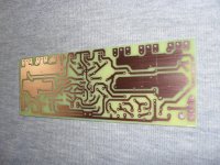
When you want to try the circuit in 2 hrs there’s no substitute to etch your own. I agree that for $2 plus $14 shipping from China, that’s what I resort to when not in a total hurry. In fact, my $2 JLCPCB order for some cap multipliers should be here in a few days. 🙂
Hi XRK971, I did this pcb with Positiv 20 its a funy work
Attachments
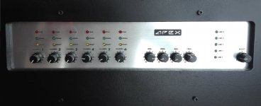

Apex HV 12,Db3 eq ,with p2 preamp good sound,56vdc rail offset 7mv ,thank you mr.apex sir for share this amp.
Nice work, HV12 is my new 'working horse'
????
I'm collecting all the possible information about HV23 and I find this in post # 77. No forum user commented on this and I do not see a thermistor on R20 in the photos of all the armed PCBs.
Apex, Is it possible to use in Q9 and Q10, MJE15030 / 31? or 2SD669A, 2SB649A?
R20 100ohm NTC
I'm collecting all the possible information about HV23 and I find this in post # 77. No forum user commented on this and I do not see a thermistor on R20 in the photos of all the armed PCBs.
Apex, Is it possible to use in Q9 and Q10, MJE15030 / 31? or 2SD669A, 2SB649A?
Last edited:
I'm collecting all the possible information about HV23 and I find this in post # 77. No forum user commented on this and I do not see a thermistor on R20 in the photos of all the armed PCBs.
Apex, Is it possible to use in Q9 and Q10, MJE15030 / 31? or 2SD669A, 2SB649A?
It is possible to use many TO220 pairs in Q9/10 and R20 is not NTC but can be MF (metal film)
Greetings
Mr.apex sir I try to make hv12 single pair output what changes i do,and how much dc use?
Mr.apex sir I try to make hv12 single pair output what changes i do,and how much dc use?
...the led indicator blink 5 times (1Hz)?
Hi, Apex There is a forum user who built the protector, delay, etc. from post 475. Then consult with you the delay time, and in the post of the appointment you ask if the led flashes 5 times.
What LED do you mean? I do not see any on the PCB. Could I go up or tell me where to find the circuit? Thanks, very kind.
Hi all. A query on the limiter VI. The transistor Q12 (Q11) needs a voltage of approximately 3V to be developed on the resistor R35 (R39) to start conducting and carrying out its current limiting work. Now, the 3v on R35 (R39) implies a current of about 6A on each power transistor. This is good?.
Another question, how many pairs of output would be necessary to operate safely in bridge over 4 ohms with a power of +/- 80V?
Thank you all.
Another question, how many pairs of output would be necessary to operate safely in bridge over 4 ohms with a power of +/- 80V?
Thank you all.

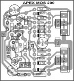
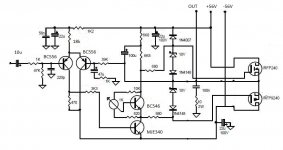
Hi, I can use only 4 mosfets instead of 8?Simple Full Complementary Simetry +/-80V. Voltage amplifier/driver biased with 30mA. This driver circuit stabilized BIAS in output stage. Exelent stability without oscilation, hum and noise, sound great.
RMS Power: 240W 8ohm, 350W 4ohm
Go to post #470 for schematic and PCB
MOSFET Amplifier IRFP240/IRFP9240
Thanks
Sir mile schematics pls. mosfet 200 thanks
Attachments
Another question, how many pairs of output would be necessary to operate safely in bridge over 4 ohms with a power of +/- 80V?
Another question, how many pairs of output would be necessary to operate safely in bridge over 4 ohms with a power of +/- 80V?
Bridged mode into 4 ohms the amp sees 2 ohm. +/- 80V into 2 ohm is 40A, 3.2kW. That is a huge load.
It still only sees 4 ohms, just that the load sees 80Vx2 or 160V(p-p) as the supply which is crazy. E squared / R
I do not know why people just do not parallel more amps vs making one big one, what speaker are you driving?
I do not know why people just do not parallel more amps vs making one big one, what speaker are you driving?
- Home
- Amplifiers
- Solid State
- MOSFET Amplifier IRFP240/IRFP9240