Hi
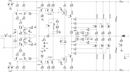
I have recently designed this amplifier schematic, which is used with a single pair of BJT. In this configuration, the performance is decent.
Anyway, the problem is that I have tried to change outputs to MOSFET and added another 2 pairs in parallel. I have readjusted the BIAS stage, so that I can gain voltage drop required.
In the simulation file (MULTISIM), everything works fine. In reality, the output stage won't work at all.
Input stage and VAS are operating fine, voltage drop across the BIAS transistor can be adjusted. As soon as I connect the mos outputs, acts like a short-circuit and the protection of the power supply kicks in.
Any suggestions, please ? 🙂
Attachments
What bias voltage do you get with mosfets removed ?
Mosfets take about 3 to 4 volts to to turn on.
So the bias voltage should be less than about 7 volts.
Start bias voltage at zero and slowly turn it up, does it work OK ?
Mosfets take about 3 to 4 volts to to turn on.
So the bias voltage should be less than about 7 volts.
Start bias voltage at zero and slowly turn it up, does it work OK ?
Yes.
With values shown, bias across Tr13 will be **at least* 7V something, adjustable to hairy 14V something, WAY too high.
Short protection circuit values are also wrong, it will trigger for load values 16 ohm and lower, so amp is unusable.
Rather than a "design" from scratch, circuit looks like copypasting bits from different circuits or a random tweaked textbook example.
Might seem to work in simulation, trusting component models, but often not in practice with real world devices.
Simulation is a powerful tool but often an approximation, by definition.
What bias voltage do you get with mosfets removed ?
Mosfets take about 3 to 4 volts to to turn on.
So the bias voltage should be less than about 7 volts.
Start bias voltage at zero and slowly turn it up, does it work OK ?
Thank you for your help. I have calculated about 9.8-10Vdc the voltage drop on the output stage (0.6V Vbe of predriver + 0.6Vbe of driver + 4V for the Mosfet)all this times 2.
Please correct me if I'm wrong. The multisim shows very similar to this as well.
Regards,
Julian
I would have thought nearer 6 to 7 volts bias voltage.
With 10 volts they will be shorting out.
The wya to test is to turn bias right down well below 5 volts to start with.
Apply a sine wave to input.
Monitor output wit ha scope.
Turn up bias slowly until there is no crossover distortion on output.
Another way of testing is to measure current through source resistors (speaker disconnected.) About 10-20mA should be enough standing current.
I have set 9.13V voltage drop across T13 which gives roughly 30mA for each pair. (10mV across source resistors)
The amp is running, but there's an HF oscillation that can be heard when connecting the speakers (like a soft hiss).
Should I increase values of C12,C13 ?
Regards
The amp is running, but there's an HF oscillation that can be heard when connecting the speakers (like a soft hiss).
Should I increase values of C12,C13 ?
Regards
- Home
- Amplifiers
- Solid State
- MOSFET Amp. Problem