Hi
I have a couple of questions.
I have gone from a 2 stage to a 3 stage design.
My old 2 stage design was a 6J5/300B design, which had a lovely tone, but I felt it needed a little more gain and that as a result it lost some bottom end control.

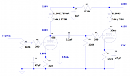
So I have gone to a Morrison 6SN7/300B design, and this has more control and WAY more gain. But despite star earth, separate signal and chassis earths, and shielded input there is quite a lot of hum, not with the input grounded, but when I turn up the 100k input pot the hum increases quite markedly.
I am sure that this is common issue with a common cause but I couldn't search it (as every thread has 'hum' in 🙂). So any pointers gratefully received.

The second question is, how to lower the gain of the morrison circuit? Do I lower the anode resistor or raise the cathode resistor of the first triode? If I can really lower the hum then I may not need this, but I am up to VERY loud at 1/2 way on the pot so dont need all the gain.
Huge thank yous for your time, and keep well!
I have a couple of questions.
I have gone from a 2 stage to a 3 stage design.
My old 2 stage design was a 6J5/300B design, which had a lovely tone, but I felt it needed a little more gain and that as a result it lost some bottom end control.

So I have gone to a Morrison 6SN7/300B design, and this has more control and WAY more gain. But despite star earth, separate signal and chassis earths, and shielded input there is quite a lot of hum, not with the input grounded, but when I turn up the 100k input pot the hum increases quite markedly.
I am sure that this is common issue with a common cause but I couldn't search it (as every thread has 'hum' in 🙂). So any pointers gratefully received.

The second question is, how to lower the gain of the morrison circuit? Do I lower the anode resistor or raise the cathode resistor of the first triode? If I can really lower the hum then I may not need this, but I am up to VERY loud at 1/2 way on the pot so dont need all the gain.
Huge thank yous for your time, and keep well!
Gain: Remove 100uf capacitor to lower the gain.
Hum: did you elevate the heater voltage of 6SN7 ?
Hum: did you elevate the heater voltage of 6SN7 ?
Hi fossa
What a speedy reply.
I will remove the 100uf. Will that reduce the bandwidth?
And the heater is 6.3v ac. Is that the problem? Do I need a dc heater voltage?
Huge thanks
What a speedy reply.
I will remove the 100uf. Will that reduce the bandwidth?
And the heater is 6.3v ac. Is that the problem? Do I need a dc heater voltage?
Huge thanks
I don’t think it is magnetic coupling as the distances and orientations are ok.
If it was the heater then would grounding the input kill the hum?
And the hum is higher than 50hz - sounds like 100 plus harmonics.
Thanks all
If it was the heater then would grounding the input kill the hum?
And the hum is higher than 50hz - sounds like 100 plus harmonics.
Thanks all
Ah - I have no DC coupling between my heaters and signal earth.A good read regarding heater hum:
The Valve Wizard
Evidently a beginners error.
Will try and find a good approach to fixing this.
That Sun Audio/"JC Morrison" design has so many problems. I've done a few videos on it and the resolution is to convert it to a cascode. IMHO that direct coupled 6SN7 setup is a really bad way to drive a 300B.
Tuning and modifying a JC Morrison style 300B DIY tube amp. - YouTube
300B Tube Amp: Final Analysis, Mods and Solutions for JC Morrison based Amplifiers. - YouTube
Tuning and modifying a JC Morrison style 300B DIY tube amp. - YouTube
300B Tube Amp: Final Analysis, Mods and Solutions for JC Morrison based Amplifiers. - YouTube
Hi stephe
Thank you for your post.
I think the issues you had with the Morrison schematic are what I am hearing.
I will certainly give your design a try.
Keep well
Thank you for your post.
I think the issues you had with the Morrison schematic are what I am hearing.
I will certainly give your design a try.
Keep well
The hum is gone after tying the heaters to signal ground through 220 resistors.
Thanks for your help. A beginners error ��
Thanks for your help. A beginners error ��
Only the heaters of the 6SN7's should be grounded. If you would ground the heaters of the 300B's you would short the cathode resistors and loose the bias. Besides that: The 300B's already have a connection to ground through the cathode resistors.
Stephe schematic question
Hi Stephe
Just a point of clarification on your schematics.
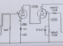
On the YouTube clip you have posted as the final analysis, you show the following schematic:

This has the led on the cathode with a 50R and a 2V grid difference on the 2nd triode.
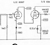
Whilst on your web site, the final schematic has this:

This has the led with a 200R and 5v grid difference on the second triode.
Is either of these actually the final schematic?
The 200R makes more sense to me as with a 4mA current it takes the grid of the first triode to 2.5V.
However, the 2V grid voltage on the 2nd triode makes sense to me as well.
I'm just about to upgrade my Morrison version to try yours and just wanted to know which version to start with.
Many thanks and keep well
Hi Stephe
Just a point of clarification on your schematics.
On the YouTube clip you have posted as the final analysis, you show the following schematic:

This has the led on the cathode with a 50R and a 2V grid difference on the 2nd triode.
Whilst on your web site, the final schematic has this:

This has the led with a 200R and 5v grid difference on the second triode.
Is either of these actually the final schematic?
The 200R makes more sense to me as with a 4mA current it takes the grid of the first triode to 2.5V.
However, the 2V grid voltage on the 2nd triode makes sense to me as well.
I'm just about to upgrade my Morrison version to try yours and just wanted to know which version to start with.
Many thanks and keep well
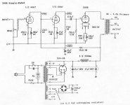
This is from another thread concerning the Shidshido circuit used by Sun Audio for the last 30 years in their commercial products:
Is it time to start calling this circuit what it really is: Sun Audio's current product?
sorry if i missed something but where in the world did this amp design become associated with jc morrison? if it was from the "fi primer", that was a collection of circuits made by various people, mainly japanese, that were popular in the 80's and 90s. this was explained clearly in the notes. i saw a schematic from "skunkie" that was a reprint of a shishido amp that was part of the "fi primer"... not a jc morrison design. not a "skunkie design". just wondering...
Is it time to start calling this circuit what it really is: Sun Audio's current product?
- Home
- Amplifiers
- Tubes / Valves
- Morrison 6SN7 300B Hum and gain questions