I contacted Suppression Devices and they make two types of the Morgan Jones (Kelvin connection) Kapacitor, 4-lead and 10-lead versions, both available in 10uF only. Does anyone know what the 10-lead version would be used for? Parralelling maybe? I didn't see them referenced in his new book.
I'm the proud owner of one of the ten legged monsters. The idea is to be able to have one set of input leads and multiple sets of output leads to feed more than one stage, each with its own dedicated set of leads.
Mine was free. 😀 Suppression can give you quotes- they're apparently not very expensive, 10 or 15 pounds.
The idea is to be able to have one set of input leads and multiple sets of output leads to feed more than one stage, each with its own dedicated set of leads.
I can see the advantage of using less space, and money
but optimally, shouldn't each output have its own cap ?
Yes, as long as they're each Kelvin connection caps. But lots of circuits don't need that so a single Kelvin cap will do. After all, not all ten leads need be used...
4 leads is universal. 10 leads is for feeding four circuits, a fairly common situation (e.g., two stage amplification, two channels).
Here's the price they quoted for 10uF:
4-leads:
1 - 4 £8.52 each
5 - 9 £7.67 each
10 - 24 £6.90 each
10 leads:
1 - 4 £9.70 each
5 - 9 £8.73 each
10 - 24 £7.86 each
4-leads:
1 - 4 £8.52 each
5 - 9 £7.67 each
10 - 24 £6.90 each
10 leads:
1 - 4 £9.70 each
5 - 9 £8.73 each
10 - 24 £7.86 each
4 leads is universal. 10 leads is for feeding four circuits, a fairly common situation (e.g., two stage amplification, two channels).
Would you be able to make a crude drawing of what that looks like? My simple caveman brain is frightened and confused by such modern concepts.
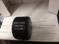
They are pretty big, this box is about 8" long. I thought I had the wrong order when they first arrived!
I spoke with Campbell at SD and he said that Morgan found significant improvement with the added leads when using multiple stages. I havn't had the chance to use them or compare them yet but I look forward to.
Strange creatures....
I spoke with Campbell at SD and he said that Morgan found significant improvement with the added leads when using multiple stages. I havn't had the chance to use them or compare them yet but I look forward to.
Strange creatures....
Attachments
In terms of electrical connections, this is outlined in great detail in Valve Amplifiers, 4th edition. Basically, it's a Kelvin connection, one set of leads go to the supply, another set go to the load- they connect right at the cap foils, reducing the effect of ESR from the leads on coupling of ripple and signal between stages.
Wasn't there a t-cap or something from Jensen with more than the obvious amount of connections? I'm talking 2004 or about.
In terms of electrical connections, this is outlined in great detail in Valve Amplifiers, 4th edition. Basically, it's a Kelvin connection, one set of leads go to the supply, another set go to the load- they connect right at the cap foils, reducing the effect of ESR from the leads on coupling of ripple and signal between stages.
After seeing pg 374 (courtesy of google books preview) I understand how a single 4 lead kelvin cap would work. For 4 stages I have trouble imagining where the 10 leads would go because the basic premise is 4 leads per cap which (after consulting with my fingers and toes) would yield 16 leads if I were to assume 4 capacitors (because of 2x2 stage/channel) and extrapolate from what I currently understand.
We have a winner
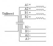
That's the idea for the ten leg but with resistors on both ends and the lead inductance added . So you did solve the cross cap puzzle.Does it look like this? Please say yes because I feel like I just solved a crossword puzzle.
The picture is of 8 leads . I am mising some here . Looked at page 374 in the book and am confused as to 4 leads on each end. Thanks for the insight .They are pretty big, this box is about 8" long. I thought I had the wrong order when they first arrived!
I spoke with Campbell at SD and he said that Morgan found significant improvement with the added leads when using multiple stages. I havn't had the chance to use them or compare them yet but I look forward to.
Strange creatures....
- Status
- Not open for further replies.
- Home
- Design & Build
- Parts
- Morgan Jones Kapacitors