I'm running this through a pair of Tekton Lores which, with 10ish watts is plenty loud enough for apartment harmony. I've been into SETs.......or ultra linear whatevers for this reason 🙂
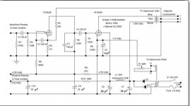
Just finished a new build based on this design. I used some unused 3.5k ohm transformers I had from a previous kit build which indicated a 46% UL tap. When testing voltages I'm seeing 331 B+, 320 at the plates but 326 at the screen. I'm assuming that I probably need a larger value resistor than the 100 ohm I've got in there based on the triode set-up of the design. Any recommendation on voltage I should be seeing at the screen and/or a resistor size I should be shooting for? I'd rather start off with some intelligently sourced ideas than keep swapping resistors in a cramped chassis. Thanks all!
Off the top it sounds like you have connected your OPT to the screen lead rather than the adjoining plate lead on the octal socket.😱
bubbazanetti,
Congratulations.
Glad you built it successfully, and are enjoying listening to it.
I built a low power amp for my computer, it uses an LM334 current sink/12AY7 phase splitter, and 6L6GC tubes in Ultra Linear push pull. Low power works fine for the near field listening I do there (about 3 feet speaker to ear).
Got a photo?🙂
Just finished a new build based on this design. I used some unused 3.5k ohm transformers I had from a previous kit build which indicated a 46% UL tap. When testing voltages I'm seeing 331 B+, 320 at the plates but 326 at the screen. I'm assuming that I probably need a larger value resistor than the 100 ohm I've got in there based on the triode set-up of the design. Any recommendation on voltage I should be seeing at the screen and/or a resistor size I should be shooting for? I'd rather start off with some intelligently sourced ideas than keep swapping resistors in a cramped chassis. Thanks all!
If your concern is that the screen is at a higher voltage than the plate, that is not a problem at all. The screen resister is meant to suppress parasitic oscillation of the output tube, as sometimes happens, especially when driving a complex load such as a loudspeaker. The 100R is OK, just needs to be carbon composition so that it still looks like a resister at RF.
Another common misconception is the need to run indirectly heated tube heater on DC. They are meant to run on AC, that is why people put a lot of effort into perfecting them. The added complexity & cost of a DC supply for IDHT is not justified at all.
And if there is hum, better start looking for defective tubes or some other problem in the system. The brute force PS in the original design of this amp is a disaster. An R between the filter C's is a good start. A small choke would be even better.
Try something like 10R in series with the PT HV & the diode bridge. And remove the paralleled caps from the diode bridge. I think your HV PS circuit is a high Q circuit, needs some resistive damping to prevent ringing in the AC HV winding. A scope would see that.🙂
I've used the basic circuit in this thread often, never with any problems. The attached amp has run in my workshop since 1968. Only a couple of 6AQ5s were ever replaced. There is no hum with AC on the heaters, even from the on board very low level magnetic phono preamp.🙂
Attachments
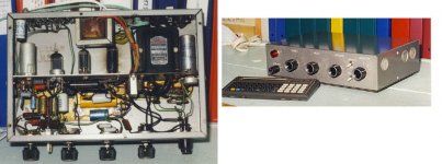
Got a photo?🙂
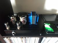
Sure! You can see how tiny this thing is, footprint is roughly equivalent to a piece of letter sized paper. Because I hardly know what I'm doing, i was able to cram all of those 330uf caps under there as well, in what is likely far less than a conventional layout which will have to wait till next time it's popped open to photograph. I did my damndest to keep all the audio stuff to the left and all the power stuff to the right.
So is the earlier suggestion (thank you) of a resistor between cap 2 and 3 and reducing caps 5 and 6 to 47uf a good place to start? I ask because I have all that stuff handy and why not make the stuffed to the gills underside a bit less stuffed?
Attachments
Haha, i don't want to say i'm not savvy enough to use/understand the emulator, but in reality, that's just it (i.e. can't seem to figure out the transformer's impedance using an ohms law calculator). I'd like to understand what I'm doing/why it makes a difference. I realize I have a massive amount of capacitance in this design, the music plays for upwards of 45 seconds after i flip the power switch, but in the end, what the was the ultimate goal of this layout? You'd mentioned brute force......is this opposed to a choke or something more conventional? I'd originally settled on this design because it didn't have a choke (see picture).
Also, how much b+ will I likely lose with that resistor? I'd try to figure it out for myself in psud, but the numbers I'm getting out of it aren't making sense to me. Thanks for all the mentoring!
Also, how much b+ will I likely lose with that resistor? I'd try to figure it out for myself in psud, but the numbers I'm getting out of it aren't making sense to me. Thanks for all the mentoring!
Last edited:
We all started at the same place with the same knowledge.
E=IR.
At about .1 amps the drop thru the 100 ohm resistor is 10v. That power supply has almost 2000uF in it. I typically see power supplies with 1/10 of that capacity that perform much better. We're calling it brute force. The opposite of finesse. Have a look at old radios and amplifier designs, designs from the 30s-60s. You'll see what I mean. You can trade 10-20 volts in the B+ for a much better result.
Last edited:
Ringing Interference
Often overlooked but easily seen on a scope, when the rectifier diode stops conducting there is no damping on the PT winding. So a resonance related to the leakage reactance of the winding, the winding capacity & stray circuit C is set up.
That can leak thru to the rest of the circuit & often does as a persistent, low level background noise at twice the supply frequency. Various RC time constants across the winding can be used to eliminate the problem. The C in the TC lowers the resonant frequency and with luck the energy in the ringing is dissipated in the R.🙂
Many RC TCs shew up in the various circuit examples, was often cut & try. Something like 10K in series with 0.01 microF is a starting point. The cap needs to be at least 600V rating, One KV is better.
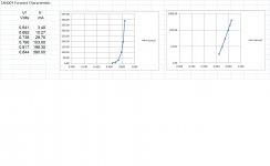
Attached are linear & log plots of a real 1N4007, on the bench. A few years ago I did Silicon, Germanium, Selenium, Red, Green & Yellow LEDs. The data here is from that group.🙂
Often overlooked but easily seen on a scope, when the rectifier diode stops conducting there is no damping on the PT winding. So a resonance related to the leakage reactance of the winding, the winding capacity & stray circuit C is set up.
That can leak thru to the rest of the circuit & often does as a persistent, low level background noise at twice the supply frequency. Various RC time constants across the winding can be used to eliminate the problem. The C in the TC lowers the resonant frequency and with luck the energy in the ringing is dissipated in the R.🙂
Many RC TCs shew up in the various circuit examples, was often cut & try. Something like 10K in series with 0.01 microF is a starting point. The cap needs to be at least 600V rating, One KV is better.
Attached are linear & log plots of a real 1N4007, on the bench. A few years ago I did Silicon, Germanium, Selenium, Red, Green & Yellow LEDs. The data here is from that group.🙂
Attachments
- Home
- Amplifiers
- Tubes / Valves
- More voltage on screen than grid?