I think you may be right about driving the lower tube with the
upper's plate then divided only by Mu, and not divide by Mu^2.
I made the wrong assumption that both tubes multiply volts
by something close to Mu, and you need divide twice to come
full circle back to follow where you started. Not quite true...
Apparently we are so far from constant current operation in
this circuit, that Mu of the lower tube is almost an irrelevant.
Obtaining equal swings of GM is what needs here.
But does it still follow faithfully? When the lower tube is driven
hard enough to be of equal current swing / impedance. We
are no longer closely tracking the upper triode's grid, nor the
lower triode's Mu. What actually happens, some push-pull of
non-linear^1.5 laws between them?
athos56 said:I should use a value higher then 1uf? Something more like 2.2uf, 3.3uf, or 4.7uf?
The impedance is probably 87 ohms in parallel with 87ohms = 43.5
I'd expect you need a pretty big cap (220uF) to drive a load of equal
impedance. Of course if the load impedance is higher, you can get
away with a much smaller cap. But then why all the trouble to make
such a low impedance drive to begin with?
--------------------------------------------------------------------------------------
kenpeter said:I think you may be right about driving the lower tube with the
upper's plate then divided only by Mu, and not divide by Mu^2.
I made the wrong assumption that both tubes multiply volts
by something close to Mu, and you need divide twice to come
full circle back to follow where you started. Not quite true...
Apparently we are so far from constant current operation in
this circuit, that Mu of the lower tube is almost an irrelevant.
Obtaining equal swings of GM is what needs here.
But does it still follow faithfully? When the lower tube is driven
hard enough to be of equal current swing / impedance. We
are no longer closely tracking the upper triode's grid, nor the
lower triode's Mu. What actually happens, some push-pull of
non-linear^1.5 laws between them?
Hi Ken,
Essentially it is as simple as you indicate, the mu of the lower tube is not quite irrelevant but you are on target wrt to gm.. The circuit actually is an excellent performer real world and well worth the trouble to fine tune. I usually load it with a resistive load approximating the load I want to drive (sometimes that is exactly what I am driving..) and tune for the lowest thd.. It is PP so you will see a distinct drop in even harmonics when the pair are balanced..
Morgan Jones has some good info on pages 111 - 115, but interestingly no discussion of choosing the right resistor value for the plate load in the upper tube. Spice can help in this regard, but only if you have an excellent tube model to work with - I've found in some instances that the resistor needed to be about twice the value I calculated and/or modeled in spice.
kenpeter said:
The impedance is probably 87 ohms in parallel with 87ohms = 43.5
I'd expect you need a pretty big cap (220uF) to drive a load of equal
impedance. Of course if the load impedance is higher, you can get
away with a much smaller cap. But then why all the trouble to make
such a low impedance drive to begin with?
--------------------------------------------------------------------------------------
I think Athos56 was actually referring to the coupling capacitor between the plate of the upper tube and the grid of the lower tube. I would recommend 0.33uF as about the maximum before cap quality issues become problematic..
In terms of output coupling cap 220uF is pretty reasonable down to 32 ohm loads or so.. I use photoflash types as they are very low ESR relative to conventional supply electrolytics - never use them where high ripple currents are present. And in headphone applications be aware that a large amount of dc is present just on the other side of that cap.. Potential hazard to be aware of..
kenpeter said:
The impedance is probably 87 ohms in parallel with 87ohms = 43.5
I'd expect you need a pretty big cap (220uF) to drive a load of equal
impedance. Of course if the load impedance is higher, you can get
away with a much smaller cap. But then why all the trouble to make
such a low impedance drive to begin with?
--------------------------------------------------------------------------------------
If I'm driving an amp with a 100k resistor at the input thats the load right?
Later he posts on the Tubecad site that the revised equation is Ra=(Rp +2RL)/mu where RL is the load
So Ra=(3k+2(100k))/16 -> Ra=203K/16=12,687.5 sooo ~12.5k
So thats more along the lines of what you were saying earlier... He stated that with a tube that had a large Rp that the change to the equasion wasn't as important, but I guess the lower Rp of the 5687 made the difference. I'm not sure if I'm mucking this up
")
I'm still researching the Rk and the coupling cap...
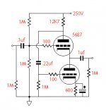
I understand that these are used for phones, but the main purpose was as a buffer for a CDP and then as a buffer/volume control for a tube amp. Maybe the first schematic is best since I don't need the super low z-out?
12K is gonna drop a lot of voltage, and far more than the cathode
bias resistor on the flip side. You may have to readjust the balance
of the 1M + 1M totem that "centers" the grid of the upper triode.
And re-figure your current and bias, etc etc. Unless you increase B+
by an amount equal to the newly calculated plate resistor's drop.
I would not trust gm of the upper triode is completely unaffected by
that much plate resistor swing. And then even if the grid signals are
equal and opposite, the lower triode's GM will never be the same.
I am sure it call all be tweaked into balance somehow, but Broskie's
maths is killin me.
-------------------------------------------------------------------------------------
Wait! He claims RP/Mu... For us, thats around 2000/18 = 112R.
But also claims 1/gm... For us thats 87R, same equation as for
cathode impedance. And I'm still lessn halfway thru the article!!!
---------ok, he then also points out that those don't agree--------
And the new Broskie formula is simply beyond my comprehension.
I will stick by the cathodyne variant I've stumbled onto, as the
math of choosing resistors for it seems far more straightforward.
Follow the link provided above he changes it again, thats where I got the 12k. I verified it in a spread sheet provided by a post I found on head-fi. I attached it. When I calculate my new Rk, which Morgan says is calculated in the usual way (read on google books, I was lucky that the preview of his book had the pages on the WCF.) I came up with 600 ohms for the Rk.
Attachments
This is about where I seem to be stuck for the moment.
Could even be right, but not ready to bet the farm on it.
I wonder if the 100uF on the right plate and cathode
need to be doubled, that the series pair looks 100uF
(through the right side triode) into the load.
The left side triode has 2K in series to muck with its gm.
I wonder if the right cathode should remain unbypassed
to put the same resistance in series with the calculation
of gm. Or is unbypassed resistance multipled by the tube
and come out wrong Z at the plate even if gm is corrected
(made compliment of the left) by it?
Do I have 87R coming up thru the right plate, or 2K(RP)?
Or both in parallel, or both in series?
I fully expect it works, I just don't know if its optimal?
Attachments
Ken, in your double cathodyne circuit in post #10, try adding a conceptual cap and resistor (in series) from V2 plate back to V1 grid. By trimming loop gain just below unity (so it doesn't oscillate), the Gm of the two approach infinity, giving perfect accuracy.
Since the input source Z will interfere with that feedback, change to a resistor between the V1 and V2 cathodes, adjusted just below oscillation. Same net effect of infinite Gm follower, so high accuracy.
(Conceptualizing here, untested)
Don
Since the input source Z will interfere with that feedback, change to a resistor between the V1 and V2 cathodes, adjusted just below oscillation. Same net effect of infinite Gm follower, so high accuracy.
(Conceptualizing here, untested)
Don
smoking-amp said:Since the input source Z will interfere with that feedback
Don
We were supposed to be following the input source, how
does that contrast with your vision of how it should work?
Note polarity of feedback from V2 plate would be POSITIVE.
I don't see how this gets us anywhere but latchup untill
the FB caps discharge, then plunge the other direction.
Lather rinse repeat.
"We were supposed to be following the input source, how
does that contrast with your vision of how it should work?"
Well, just that a zero input Z source would overide the positive feedback path altogether.
"Note polarity of feedback from V2 plate would be POSITIVE.
I don't see how this gets us anywhere but latchup untill
the FB caps discharge, then plunge the other direction.
Lather rinse repeat."
Yes, positive feeedback is intended. It needs a little fixup with a LF limiting cap in series with the positve feedback resistor (between cathodes) so that the other caps don't lead to bistability at low frequency. The feedback gets adjusted to just below a loop gain of one, ie, just below oscillation. Gives high effective Gm then.
Don
kenpeter said:Ouch. There's a huge difference in drive levels if the left cathode is
allowed to track, and the right is not. I gotz to go re-figure again.
It almost doesn't matter with what ratio you feed V2's grid, as
long as its in the ballpark. There is a true cascode above it (or
virtual one beside it) to multiply a negative feedback that will
correct any error.
Without the positive feedback, the cathode followers require some grid to cathode drive signal due to finite Gm. So the final output gain will be a little less than 1.
With the positive feedback, the gain can be brought up to within a flea's f_rt of unity gain. The high effective Gm then should also lower distortion further. (not that there's much dist. to fix, but you know..., the old complaints about CFs sounding bad....).
Don
With the positive feedback, the gain can be brought up to within a flea's f_rt of unity gain. The high effective Gm then should also lower distortion further. (not that there's much dist. to fix, but you know..., the old complaints about CFs sounding bad....).
Don
ErikdeBest said:
Ahhh, another answer, lower down on this page he recomends running without a cathode bypass. I just had to read the page 3 times
to see it.Attachments
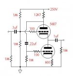
your right the 12k would drop a lot of voltage, maybe I should stick to Ra=rp/mu. Come to think of it, that would mean that Kevin was right and that the second schematic I posted was likely about right. I should just try that one instead of trying to muck with it. There is always the first, really simple one as well...
athos56 said:your right the 12k would drop a lot of voltage, maybe I should stick to Ra=rp/mu. Come to think of it, that would mean that Kevin was right and that the second schematic I posted was likely about right. I should just try that one instead of trying to muck with it. There is always the first, really simple one as well...
I agree, and I would give that circuit a try, I'm not sure what JB is on about here, but my gut feeling is that something is amiss with his math... (That would be pretty unusual - brilliant fellow in general.) I've used the bog standard circuit in several applications and it seems to work pretty much as advertised in old text books..
Hmm, I wonder if Terman might have the answer you seek?
- Status
- This old topic is closed. If you want to reopen this topic, contact a moderator using the "Report Post" button.
- Home
- Amplifiers
- Tubes / Valves
- More Tube Learning (for me) Cathode followers