If you haven't altered the working point for the CFs, the amp will run in a sort of class B with quite a lot of cross over distortion.
Just my 0.02% THD 🙂
Just my 0.02% THD 🙂
I have put there an 1.2Meg resistor, just forgot to draw it to the schematic 🙂
Thank yor for reminding me! I gonna put it into the schematic
Thank yor for reminding me! I gonna put it into the schematic
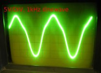
I have made a few pictures from my 'scope, here's the first
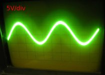
I measured the output waveform on the output-transformer. The trafo was loaded with a 8ohm dummy-load.
The upper side of the sine-wave is very distorded.
The bottom-side is good.
There's one strange thing... There are two trim-pots in the circuit, I can adjust the quiescent current of the tubes. One of them I can set the quiescent current in a wide range, from a few milliAmps to almost 70-80milliAmps. That trim.pot belongs to the tube, which produces the bottom part of the sine-wave on the pic.
With the other one I can adjust the I_q only from a few mA to about 25mA. And this trim.pot belong to the tube, wich "produces" the upper side of the sine-wave.
Yes, I have tried to exchange that tube to another, but the results were the same.
Why is this? Is it normal?
Attachments

Danko said:I have put there an 1.2Meg resistor, just forgot to draw it to the schematic 🙂
What jane said. The CF design has to be redone; they're running a poor class B. And the 6H8 may not alone have enough swing to drive the grids nor enough gain.
Hi!
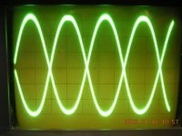
I observed varefully the signal on the CF, and I noticed a small distortion on the one part.
This is becouse I had to adjust to -40V the one Pl509's grid bias. The scope was in 20V/div, so the CF was producing about 60V signal, whish was applied to the PL509. -40V + 60V = +20V, so there was some grid-current flowing.
Now I have put this stuff away for a while, I have other things to do...
I would like to say thank you to jane, ilimzn, SY, Giaime!
in posting order🙂
I've attached the waveform on the cathode-follower. You can see the distortion on the second and fourth sine-wave.
Attachments
- Status
- Not open for further replies.
- Home
- Amplifiers
- Tubes / Valves
- more gain needed -> how?