AJT, I understand that. What is important about that article is bandwith.
And Sy, I've talked to a few people that told me to find a vintage pair of EF86 that do not suffer from micophonics will be difficult and expensive. I did find a quad of winged C EF86 on ebay. Supposedly they were made in the 80's. Ever heard them?
In a box of old tubes I found a bag of 6BH6's.
And Sy, I've talked to a few people that told me to find a vintage pair of EF86 that do not suffer from micophonics will be difficult and expensive. I did find a quad of winged C EF86 on ebay. Supposedly they were made in the 80's. Ever heard them?
In a box of old tubes I found a bag of 6BH6's.
For 120 watts, headroom is a must. I am a long tail man.
I think you would find the performance of Mr. Isodyne mediocre, judging from the look of the topology. I would pass up on hiring him.
I think you would find the performance of Mr. Isodyne mediocre, judging from the look of the topology. I would pass up on hiring him.
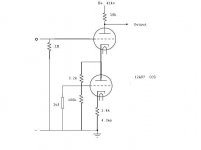
I've attempted to design a 12AU7 preamp stage for my Mark VI. I've attached a JPEG of it and would appreciate any comments you might have? When I get this finalized this I'll design the LTP
Attachments
Last edited:
I assembled a pair of MKVI in the 1970's - - the lack of individual biasing was a problem plus one of the chassis was missing holes for one transformer. Those transformers should be good and far better than Hammond. The amp sure had the potential to be great and sounded pretty good stock on classical piano lps. More capacitance after the choke was helpful.
AJT, I was adapting a design I found in Morgan Jones. I could have done it as a source rather than a sink by putting it above the signal tube. But I like the scarcity of components around the signal tube. I figured that a bypass cap for the cathode resistor should be about 150uf but with the cap on the grid it seemed unnecessary. I honestly don't know if its right, my design experience is really limited.
And freddi, I installed individual biasing and am using KT88's instead of 8417's. And I have some really huge computer grade caps in the power supply. And even though Hafler had left Dynaco by the time these were built I can't see Dynaco selling crap transformers.
And freddi, I installed individual biasing and am using KT88's instead of 8417's. And I have some really huge computer grade caps in the power supply. And even though Hafler had left Dynaco by the time these were built I can't see Dynaco selling crap transformers.
Last edited:
Hey Guys,
I finished the power supply and corrected some other problems in the first amp. With individual coupling caps bias became a snap. AC balance adjustment is another story. I'm assuming that when adjusting AC balance you input a sign wave and match the AC signal from the plates of the long tail pair. In trying to adjust this design the output from the in-phase grounded grid side is about 20% lower than the out of phase tube. In this design there are two 27k plate load resistors. Between B+ and the in-phase load resistor is a 20k pot. The schematic I have has the B+ attached to one end, the output attached to the other, and the wiper attached to the output end leg. This doesn't seem right at all.
I plan to attach the B+ to the wiper and the ends to the load resistors, ala Marantz 8b and Model 9. Does that sound like a good idea?
Also, the common cathode resistor is 1.2k and the "tail" resistor is a 12k. It seems the common cathode should be smaller and the "tail" larger. The cathode resistor still sets the operating point doesn't it?
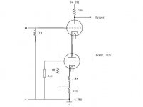
Fixed it. The original design used 27k load resistors. I changed the in-phase load resistor from 27k to 33k to get more gain. After that it was easy to balance the LTP.
Hey,
If anyone is still interested. The 6CG7 would be a good choice but I'd rather stick with something still in production. Has anyone used a 6922 as an LTP phase splitter? It would have more than twice the gain of either 12AU7 or 6CG7/6SN7, Plus I think it has a low output impedance.
If anyone is still interested. The 6CG7 would be a good choice but I'd rather stick with something still in production. Has anyone used a 6922 as an LTP phase splitter? It would have more than twice the gain of either 12AU7 or 6CG7/6SN7, Plus I think it has a low output impedance.
Hello Everyone,
I bought a bunch of RCA cleartop 6CG7's and am using those as both voltage amplifier and phase splitter. I have 5ma on the voltage amplifier, which seems high, and 3.5ma on each side of the phase splitter. Would less amperage on the voltage amplifier be better? It seems when I manipulate the resistors the amperage goes up and the bias voltage goes up. Any way I can lower the amperage without moving the bias point.
And is 3.5ma per side on the phase splitter enough to drive KT88?
- Status
- Not open for further replies.
- Home
- Amplifiers
- Tubes / Valves
- More Dynaco Mark VI Questions