This is extremely promising.
One of my first simulations back in 2008 - to fix a real amp , combined with one
of my latest design techniques ... the CFA.
I most likely won't build this myself ... I have seen the OPS of this work and
I know the VSSA CFA works. So 99%-100% that the below schema will
work - and work extremely well.
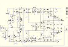
I will explain the OPS ... The differentials in the OPS (Q16/17 -Q22/23)
take the VI error signal
as local feedback (NFB) to force the "unsuitable" vertical FET's into better
"behavior". The current mirrors (Q14/15 -Q24/25)
increase the gain of this local feedback to the point of an OPS with 40ppm
THD20 in isolation.
The current sources (Q18-21) also help to lower PSRR of the output stage.
This is a "burning amp" 😀 ... the 4 pair genesis needed
a 1kva trafo and 20cm squared of aluminum heatsink. The amp heated my
WHOLE living room in winter .... but sounded like "heaven".
Below is schema + ASC.
PS - R28/Q13 will adjust IRFPxxxx idle current between 2.1A and 4 A.
This amp will do 4ppm 1K and 40ppm 20K /4R full power. THD is almost ALL
H2 ! Also ... this is a VERY high power Class A amp , 150w-8R ... 300w+ 4R.
OS
One of my first simulations back in 2008 - to fix a real amp , combined with one
of my latest design techniques ... the CFA.
I most likely won't build this myself ... I have seen the OPS of this work and
I know the VSSA CFA works. So 99%-100% that the below schema will
work - and work extremely well.
I will explain the OPS ... The differentials in the OPS (Q16/17 -Q22/23)
take the VI error signal
as local feedback (NFB) to force the "unsuitable" vertical FET's into better
"behavior". The current mirrors (Q14/15 -Q24/25)
increase the gain of this local feedback to the point of an OPS with 40ppm
THD20 in isolation.
The current sources (Q18-21) also help to lower PSRR of the output stage.
This is a "burning amp" 😀
... the 4 pair genesis neededa 1kva trafo and 20cm squared of aluminum heatsink. The amp heated my
WHOLE living room in winter .... but sounded like "heaven".
Below is schema + ASC.
PS - R28/Q13 will adjust IRFPxxxx idle current between 2.1A and 4 A.
This amp will do 4ppm 1K and 40ppm 20K /4R full power. THD is almost ALL
H2 ! Also ... this is a VERY high power Class A amp , 150w-8R ... 300w+ 4R.
OS
Attachments
Nope , every device is essential .
Without the CCS's and current mirrors , the CFA PSRR sucks ! The other option
is to power the CFA with it's own supply (little 30va trafo -50-0-50V).
OR run a "badger" (blameless) as the IPS ! This will give ABSOLUTE 0 THD !
There , I said it .... 0 THD. The simulator could not measure any distortion
with this OPS hooked to a blameless ! 😱
PS - I just thought the CFA's "sound" would go good with this class A setup ?
OS
Hi,
seems to me that the currents through Q17 and Q23 are a bit low to drive a triple of the MOSFETs sufficiently ´fast.
Also the idle current is too high for the heat power losses of the MOSFETs.
On the other hand the voltage losses over the MOSFETs are quite high, reducing efficiency.
Sim showed some nasty spikes in the MOSFETs currents as soon as they tend towards class AB, or cutoff.
Sorry to say, but it seems to me that the feedback is required here to clean up a otherwise not well functioning topology.
jauu
Calvin
>Sim showed some nasty spikes in the MOSFETs currents as soon as they tend towards class AB, or cutoff.
Of course. This kind of output stage is incompatible with class-AB or class-B.
BTW, a long time ago, Ed Cherry has built such an OPS.
Cheers, E.
Of course. This kind of output stage is incompatible with class-AB or class-B.
BTW, a long time ago, Ed Cherry has built such an OPS.
Cheers, E.
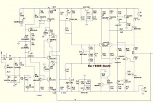
It has limitations ...
(below) is the schema for this OPS that will do 100K+ and not "misbehave"
too much on overload.
I see now why genesis used 4 of these in parallel and relied on the
bandwidth restriction of the jensen audio transformer feeding the OPS.
One pair (maybe 2 ) of IRFP per stage is all "she can take" (FET capacitance).
Going back to the original Genesis topology actually gives the best performance.
CM gave the diff. to much local FB gain.
below is a copy of my models(OSmodel.txt ... paste into "CMP" LT folder (Qstandard). Most models are LT included.
If you were to parallel a few of these (like in the original Genesis) , it would
be pretty good. Not my "cup of tea" - my electrical bill is already too high ! 😀
OS
Attachments
- Status
- Not open for further replies.
- Home
- Amplifiers
- Solid State
- Monster Class A (Genesis OPS)