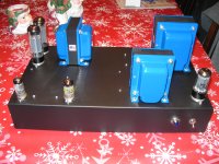
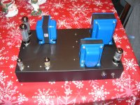
So I am building a pair of monoblocks on a steel Hammond chassis that measures 17" x 10" x 3". The design is similar to the Mullard 5-20 amplifier. I can't fit the choke under the hood so I am going to mount it on top. I went with Edcor iron so the choke looks nice enough to be on top, the blue end bells with the black chassis looks good") . I pretty much have my layout done and plan on posting some pics but I have a question about transformer placement I plan on having the cores line up as such:
. I pretty much have my layout done and plan on posting some pics but I have a question about transformer placement I plan on having the cores line up as such:
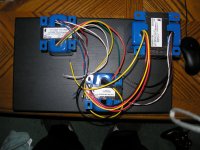
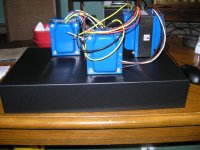
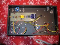
So the output and power transformer are on the back side of the chassis with the choke up front. The choke will be between the rectifier tube and the preamp tubes. The power tubes will be on the outer side of chassis next to the output transformer.
Does this seem OK? Any advice would be great before I start drilling holes.
thanks
. I pretty much have my layout done and plan on posting some pics but I have a question about transformer placement I plan on having the cores line up as such: So the output and power transformer are on the back side of the chassis with the choke up front. The choke will be between the rectifier tube and the preamp tubes. The power tubes will be on the outer side of chassis next to the output transformer.
Does this seem OK? Any advice would be great before I start drilling holes.
thanks
Attachments
Last edited:
From what I read in Morgan Jones book, the choke is the highest emitter of EM fields...that said, it should be tucked into the farthest corner of any chassis, away from everything as much as possible.
______________________________________________________Rick.........
______________________________________________________Rick.........
Last edited:
What tubes are you using?
Tubes are EF86 gain stage directly coupled to 12AX7 LTP PI driving KT77 PP/23% screen taps. Rectifier tube is 5AR4.
From what I read in Morgan Jones book, the choke is the highest emitter of EM fields...that said, it should be tucked into the farthest corner of any chassis, away from everything as much as possible.
______________________________________________________Rick.........
Thanks I will read up on that and maybe change my layout if it will help.
I was looking at some of the mono-blocks now on the Audio Note Kits site: ANK Audiokits - The Authority in High End Audio Kits
The choke on the "ledgend" and "interstage" designs seems very close to the interstage, I'd wonder about that. However, it is as far from the input tube as practical. There are other designs, like Sun Audio 2A3 that wedges the choke between power and output transformers, and much closer to input tubes.
The choke on the "ledgend" and "interstage" designs seems very close to the interstage, I'd wonder about that. However, it is as far from the input tube as practical. There are other designs, like Sun Audio 2A3 that wedges the choke between power and output transformers, and much closer to input tubes.
If at all possible, mount the choke on the side wall. Doing so allows the coil of the choke to be perpendicular to the coils of the other magnetics. Take full advantage of all 3 spatial dimensions.
If the side wall is not available, mount the choke at 45o to both the power and O/P transformers.
If the side wall is not available, mount the choke at 45o to both the power and O/P transformers.
If at all possible, mount the choke on the side wall. Doing so allows the coil of the choke to be perpendicular to the coils of the other magnetics. Take full advantage of all 3 spatial dimensions.
If the side wall is not available, mount the choke at 45o to both the power and O/P transformers.
The choke is a hair larger than 3" and the chassis is only 3" deep. I can maybe figure out a way to mount it on the sidewall but it will be TIGHT. I really like the 45 degree idea and might have to go with that if I can't use the sidewall.
If the choke is so very close to the 3" available underneath, couldn't you fabricate a simple wooden riser applied to the bottom edges of the enclosure to give you that extra clearance??..... using some of that readily available "edge trim" we see at the "home improvement" stores.
_____________________________________________________Rick........
_____________________________________________________Rick........
If the choke is so very close to the 3" available underneath, couldn't you fabricate a simple wooden riser applied to the bottom edges of the enclosure to give you that extra clearance??..... using some of that readily available "edge trim" we see at the "home improvement" stores.
_____________________________________________________Rick........
Yes great idea! I was brainstorming ideas while drinking beer and watching football
I will update my progress on the builds and still as always open to ideas and comments.
Thanks for the insight so far.
So here we have the PT and choke laminations lined up and the OPT different. The chassis I chose is bigger than this example and if I remember correctly the hum induction is reduced in a squared function the greater the distance apart from one another so I think I might be ok.
On my layout the PT and choke are about 3" inches apart and the OPT is 6" away from choke and 7" away from PT.
On my layout the PT and choke are about 3" inches apart and the OPT is 6" away from choke and 7" away from PT.
Attachments
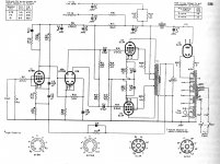
Yes here is the circuit, I upped the PS filtering to, C15-50uf, C12-100uf, C5-50uf, and C4-50uf. I wanted to see what I get for results with the basic topology, later I might implement a CCS at the LTP. The input sensitivity is 220mV for the rated 20 watt output. I plan on using a passive preamp with modern line stage 2vrms sources. I was curious if anybody made the EF86 screen switchable for triode operation?
Attachments
- Status
- This old topic is closed. If you want to reopen this topic, contact a moderator using the "Report Post" button.
- Home
- Amplifiers
- Tubes / Valves
- Monoblock project