Hi there guys,
I'm 85% done with my vintage radio restoration/re-purposing. While working out all of the kinks I finally let it play some music yesterday to see where the radio is going so far and I'm torn with something. Right now I have it set up as Stereo, which originally the radio was MONO.
My issue is I want Mono for the oldies and that nostalgic sound and Stereo for the more modern tunes. With that said, I was thinking of incorporating a MONO / Stereo Switch.
Right now the Audio is via an input 3.5mm from a Bluetooth Module going to the Amp that is a Stereo Amp. Is there a switch I can place at the 3.5mm point going to the Amp that will switch it from Mono to Stereo?
Something like this but without the Volume portion as I want that controled by the Amp POT or the Bluetooth Device. Will this even work, of course I dont want it to be 10ft long but I guess I can splice it.
http://www.vetco.net/catalog/images/PH-70-023-2.jpg
Any ideas?
I built my own stereo to mono converter and added a DPDT toggle switch to switch between Stereo and mono .
It works great. 🙂
Personally, mine evolved and I built a separate switch box containing the A/B toggle.
However, you can add the toggle at the input bypassing the circuit..
It works great. 🙂
Personally, mine evolved and I built a separate switch box containing the A/B toggle.
However, you can add the toggle at the input bypassing the circuit..
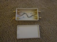
Attachments
Last edited:
Sad part is I dont even know what you just said LOL. Half the time I feel I'm in way over my head when it starts thinking.
JoeDJ, do you think the device I looked at will work? It's only 7 dollars and probably will save me a few bottles of rogaine.
http://www.vetco.net/catalog/images/PH-70-023-2.jpg
JoeDJ, do you think the device I looked at will work? It's only 7 dollars and probably will save me a few bottles of rogaine.
http://www.vetco.net/catalog/images/PH-70-023-2.jpg
I built my own stereo to mono converter and added a DPDT toggle switch to switch between Stereo and mono .
It works great. 🙂
Personally, mine evolved and I built a separate switch box containing the A/B toggle.
However, you can add the toggle at the input bypassing the circuit..
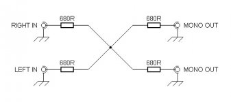
Whats the DOT in the middle of your picture? Is the In from the POT then to the swtich, then the OUt is from the Switch to the Amp?
The "dot" represent where all the resistors are joined together.
This is what gives you mono.
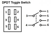
BTW here is a DPDT wiring diagram that you need..
Keep in mind that everything gets a common ground .
It's all very simple really.... don't let it scare you.
I any event, the hardware that you linked to will definitely work also. 🙂
This is what gives you mono.
BTW here is a DPDT wiring diagram that you need..
Keep in mind that everything gets a common ground .
It's all very simple really.... don't let it scare you.
I any event, the hardware that you linked to will definitely work also. 🙂
Attachments
Last edited:
The "dot" represent where all the resistors are joined together.
This is what gives you mono.
BTW here is a DPDT wiring diagram that you need..
It's all very simple reall.....y don't let it scare you. 🙂.
Ha, definitely scary stuff as I'm totally new to all of this, it's taken me close to two months to get my radio at 80%. Now I'm thinking of doing this. I'll have to absorb your second diagram and make sure I understand. Have to figure out what the 1-6 wiring layout would be. I've gotten 80% for so far. Might play around with this with the next radio as I have another linedup. Dying to get the other 20% done.
Thanks JoeDJ
One last thing, Does this turn one speaker off or simply make them both play at that "MONO" tone? Want to make sure it's not MONO as in one speaker and simply mixing the signal to one speaker.
In the diagram 3 & 4 are the inputs L&R
1 & 2 are the outputs L&R for one output
5 & 6 are the outputs L&R for the second output
So, the switch allows you to switch between two outputs .
In your case, it can it can feed your inputs into the mono converter or switch the inputs to bypass the converte.
Yeah, it can all be scary when new but is all very simple once you get into it .🙂
It can be a great learning experience that you can apply to other things.. Of course, you would have to be fairly good a soldering.
EDIT:
It will feed mono or stereo to both speakers .
Last edited:
Wow, thanks a million for clarifying it for me, much better. Last question, no ground wiring needed here on the switch?
Wow, thanks a million for clarifying it for me, much better. Last question, no ground wiring needed here on the switch?
No..
All stereo connections get a common ground ..
All stereo jacks, plugs, wires, circuits have a ground and a all grounds are connected together in what is referred to as a "common ground" .
In the case the case of a RCA plug/jack for example, the outside connection is the ground and the center connector in the "hot' wire.
So , you just would connect all the ground connections on the jacks together and all switching is done with just the "hot" wires .
Perhaps this can clarify things a bit for you....
It's the same circuit but it shows how all grounds are joined together..
All input and output jacks grounds are also connected to the same common ground together.
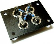
Attachments
Last edited:
No..
All stereo connections get a common ground ..
All stereo jacks, plugs, wires, circuits have a ground and a all grounds are connected together in what is refereed to as "common ground" .
In the case the case of a RCA plug foe example, the outside connection is the ground and the center connector in the "hot' wire.
So , you just would connect all the ground connections on the jacks together and all switching is done with just the "hot" wires .
PERFECTTTTTTTTTTTTTTT!!!!!!!!!!!!!!!!!!! You're right, doesnt seem that hard.
- Status
- Not open for further replies.
- Home
- General Interest
- Everything Else
- Mono / Stereo Switch