Oops...
Hello AndrewT,
Sorry, I missed that... Thanks for pointing out. What should be the fuse rating required for the whole arrangement ?
Best regards,
Bins.
Hello AndrewT,
Sorry, I missed that... Thanks for pointing out. What should be the fuse rating required for the whole arrangement ?
Best regards,
Bins.
it's shown in post29. Do you not read?
Hi,
as low a value as will allow the transformer to start without nuisance blowing.
Start with Time delayed Fuse rating = VA/Vac
as low a value as will allow the transformer to start without nuisance blowing.
Start with Time delayed Fuse rating = VA/Vac
Few more questions...
Hello AndrewT/Owen,
1. Is CL-60 thermistor (http://www.gesensing.com/downloads/datasheets/920_325a.pdf) enough ?
2. What should be the fuse rating required for the supply ?
3. Do we need that mute circuit section for reducing the speaker clicks during startup or shutdown ?
Best regards,
Bins.
Hello AndrewT/Owen,
1. Is CL-60 thermistor (http://www.gesensing.com/downloads/datasheets/920_325a.pdf) enough ?
2. What should be the fuse rating required for the supply ?
3. Do we need that mute circuit section for reducing the speaker clicks during startup or shutdown ?
Best regards,
Bins.
Hi Bins,
1. The CL-60 would be fine for what you're doing, but if you have trouble finding it then Ametherm makes the same parts. Just look for anything from 5 ohms to 10 ohms, and around 5 amps of current capacity.
Just so it's clear, the thermistor replaces the relay and resistors shown in National's circuit. There's no need to use both.
2. You can probably get away with 1A providing your line voltage is around 230VAC.
3. In my experience with the LME, you probably won't need the mute signal, but your luck may vary. The circuit shown on the National sheet you posted is pretty simple, and you can fine tune it to whatever delay you want. If you're making a PCB, add in the placeholders for the parts, if you're wiring point to point, just try without it, and if it pops, then add it in later. All it takes is two resistors, one zener, and a cap. National specs the current that needs to flow into the MUTE pin for the chip to become active, so you can work the values backwards from there. If you're only driving one LME, which with monoblocks you will be, then you can optimize those parts for one chip and the rail voltage you'll be using.
Cheers,
Owen
Inrush control...
Hello Owen,
1. CL-60 is readily available in Farnell. Please let me know what all elements should be avoided from the National's app note for implementing the suggested inrush control. I think the 3 68 Ohms resistors, capacitor C4 and the relay forms the National version. Do I also need to omit the D1 diode ? Please confirm.
2. My supply is servo regulated and will be 230 VAC.
Best regards,
Bins.
Hi Bins,
1. The CL-60 would be fine for what you're doing, but if you have trouble finding it then Ametherm makes the same parts. Just look for anything from 5 ohms to 10 ohms, and around 5 amps of current capacity.
Just so it's clear, the thermistor replaces the relay and resistors shown in National's circuit. There's no need to use both.
2. You can probably get away with 1A providing your line voltage is around 230VAC.
3. In my experience with the LME, you probably won't need the mute signal, but your luck may vary. The circuit shown on the National sheet you posted is pretty simple, and you can fine tune it to whatever delay you want. If you're making a PCB, add in the placeholders for the parts, if you're wiring point to point, just try without it, and if it pops, then add it in later. All it takes is two resistors, one zener, and a cap. National specs the current that needs to flow into the MUTE pin for the chip to become active, so you can work the values backwards from there. If you're only driving one LME, which with monoblocks you will be, then you can optimize those parts for one chip and the rail voltage you'll be using.
Cheers,
Owen
Attachments
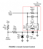
replace Rir1-3 with the CL60.
I prefer to bypass the soft start device whether it's a resistor or a thermistor.
A single CL60 does give some peak current reduction.
For 240Vac I would recommend two CL60 in series to reduce the peak current even more and thus allow a smaller fuse.
I prefer to bypass the soft start device whether it's a resistor or a thermistor.
A single CL60 does give some peak current reduction.
For 240Vac I would recommend two CL60 in series to reduce the peak current even more and thus allow a smaller fuse.
Hello,
I will be using a 1A fuse along with 2 CL-60 for the peak current reduction mechanism implementation. While using the CL-60, do we need the C4 capacitor ? Is that used to reduce the supply noise ?
Best regards,
Bins.
I will be using a 1A fuse along with 2 CL-60 for the peak current reduction mechanism implementation. While using the CL-60, do we need the C4 capacitor ? Is that used to reduce the supply noise ?
Best regards,
Bins.
replace Rir1-3 with the CL60.
I prefer to bypass the soft start device whether it's a resistor or a thermistor.
A single CL60 does give some peak current reduction.
For 240Vac I would recommend two CL60 in series to reduce the peak current even more and thus allow a smaller fuse.
Hi Guys,
Not to butt heads with AndrewT or anything, but IMHO it's not really worth the added parts and hassle to bypass those thermistors with a relay. I generally find relays to be the single most unreliable part of any amplifier (I say this from production experience) where thermistors will seldom ever cause you a problem. So what I'm trying to say is that bypassing a reliable functional solution with a less reliable solution isn't really advisable.
The thermistors will run hot all the time, just like they're supposed to. Keep that in mind when you're laying things out. Don't put them near your electrolytic caps, or any other part for that matter.
By the way Bins, are you making a PCB for this, or are you wiring point to point?
Cheers,
Owen
Hello Owen,
I will not be using the relays in my power supply. I would like to have a mute section like the one shown in the original application note. But, I am not sure on how to tweak that for the alternate supply we are discussing. Will look into that later once all other points are fixed. Instead of PCB, I prefer point to point wiring using ultra pure silver wires.
Best regards,
Bins.
Hi Guys,
Not to butt heads with AndrewT or anything, but IMHO it's not really worth the added parts and hassle to bypass those thermistors with a relay. I generally find relays to be the single most unreliable part of any amplifier (I say this from production experience) where thermistors will seldom ever cause you a problem. So what I'm trying to say is that bypassing a reliable functional solution with a less reliable solution isn't really advisable.
The thermistors will run hot all the time, just like they're supposed to. Keep that in mind when you're laying things out. Don't put them near your electrolytic caps, or any other part for that matter.
By the way Bins, are you making a PCB for this, or are you wiring point to point?
Cheers,
Owen
Inserting an extra source resistance into the transformer's primary circuit will affect the secondaries performance.
Making that source resistance variable, i.e. using a Power Thermistor, just compounds the problem.
I have actually measured the modulation of the PSU output voltage due to current changes in the un-bypassed Thermistor.
The effect even shows in the way the slightly clipped sinewave output signal changes due to the Thermistor effect.
Removal or bypassing the Thermistor allowed a bigger unclipped output sinewave.
Hi,
So what is the best solution available ?
Best regards,
Bins.
I like Bryston's Triac solution. U can download their schematics on their website.
With kind regards,
Bas
So what is the best solution available
bypass the soft start device whether it's a resistor or a thermistor.
Hello AndrewT,
1. Then how can we control the initial inrush current ?
2. How to reduce the turn on and turn off click sounds on the speaker ?
3. Do we need a speaker protection circuit ?
Best regards,
Bins.
1. Then how can we control the initial inrush current ?
2. How to reduce the turn on and turn off click sounds on the speaker ?
3. Do we need a speaker protection circuit ?
Best regards,
Bins.
Hi,
Found a paper on transformer inrush controls: http://www.powersupplyconsultants.com/INRUSH.pdf
Best regards,
Bins.
Found a paper on transformer inrush controls: http://www.powersupplyconsultants.com/INRUSH.pdf
Best regards,
Bins.
Hi,
Nice paper from Audio Amateur Corporation on designing power supplies is available at: http://www.pmillett.com/images/ga_powerline.PDF
Best regards,
Bins.
Nice paper from Audio Amateur Corporation on designing power supplies is available at: http://www.pmillett.com/images/ga_powerline.PDF
Best regards,
Bins.
- Status
- Not open for further replies.
- Home
- Amplifiers
- Solid State
- Mono blocks using National LME49830