Greetings
I am planning on building a couple of mono block power amplifiers for my home stereo system. I am not an electronics expert but have
built several electronic projects (mostly tube based) and have a good working knowledge. I have based the design on my two channel
amplifier (40 Watts to 50 Watts per channel). I recently acquired some new speakers that require a bit more power than my two channel
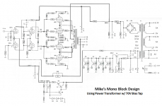
power amplifier provides. The design of the mono blocks uses four KT88 tubes in a push pull configuration for the power stage. The
design is essentially the same as the two channel system except I have added a second set of KT88 power tubes in parallel with the
original set (see the included schematic). I have a few questions:
1.) What is the powwer output of this design? I believe that it will double the outout of the two channel amp to 80 - 100 Watts.
2.) Do I need to change the value of any of the resistors in the power stage? The current design uses the same value resistors that
are present in the two channel amplifier.
3.) I have in my inventory two ultra linear output transformers rated at 60 Watts. Would it be OK to use these in the mono block for
testing purposes? If everything works OK I would upgrade to higher wattage transformers.
4.) I plan to use etched PC boards for mounting the components. Given the current requirements of the design I think 1 OZ. copper
clade would work, but should I consider 2 OZ.?
Thanks for your help and advice.
Mike
I am planning on building a couple of mono block power amplifiers for my home stereo system. I am not an electronics expert but have
built several electronic projects (mostly tube based) and have a good working knowledge. I have based the design on my two channel
amplifier (40 Watts to 50 Watts per channel). I recently acquired some new speakers that require a bit more power than my two channel
power amplifier provides. The design of the mono blocks uses four KT88 tubes in a push pull configuration for the power stage. The
design is essentially the same as the two channel system except I have added a second set of KT88 power tubes in parallel with the
original set (see the included schematic). I have a few questions:
1.) What is the powwer output of this design? I believe that it will double the outout of the two channel amp to 80 - 100 Watts.
2.) Do I need to change the value of any of the resistors in the power stage? The current design uses the same value resistors that
are present in the two channel amplifier.
3.) I have in my inventory two ultra linear output transformers rated at 60 Watts. Would it be OK to use these in the mono block for
testing purposes? If everything works OK I would upgrade to higher wattage transformers.
4.) I plan to use etched PC boards for mounting the components. Given the current requirements of the design I think 1 OZ. copper
clade would work, but should I consider 2 OZ.?
Thanks for your help and advice.
Mike
Attachments

Audio power out is a function of several things. Power in, load impedance and class of operation. In theory doubling the tubes will double the available output. Pragmatically it's often a little less. And if you double the tubes, you need to half the load impedance. The general rule of thumb is higher load impedance provides less power transfer along with lower distortion. Lower load impedance is vice versa. All this is to a point. Everything in amplifier design is a compromise to some degree. So it is our job to reach an acceptable medium.1.) What is the powwer output of this design? I believe that it will double the output of the two channel amp to 80 - 100 Watts.
I have an amplifier that uses a pair of 6550A's running at 600 volts in UL mode and a 4K ohm load. On a good day I can get 100 clean watts. Do NOT do this with today's tubes. They won't survive. Typically a quartet of 6550's/KT88's run at 60mA and 500 volts will give you around 120 watts. It really comes down to how hard you want to push things.
Essentially no.2.) Do I need to change the value of any of the resistors in the power stage?
Without knowing the specifications of your transformers you take a chance of overpowering them. You will be doubling the primary current putting them at risk. And the load impedance will be incorrect. (high) Typically tube current in an amplifier like this is around 60mA each for class AB1. Will your transformer allow twice that? If it's a decent one, probably yes.3.) I have in my inventory two ultra linear output transformers rated at 60 Watts. Would it be OK to use these in the mono block for
testing purposes?
Depends. If you plan to run filament current for the tubes on the board, then yes use the heavier copper. If not, no problem. I don't like any high heat tubes on circuit boards. And NEVER output tubes.4.) I plan to use etched PC boards for mounting the components. Given the current requirements of the design I think 1 OZ. copper
clade would work, but should I consider 2 OZ.?
Something else. Fixed bias is good and needed if you want best efficiency. But I personally don't like the idea of feeding each tube through a transistor. Especially if there is no individual voltage adjustment. Without that you must rely on matched tubes to keep the balance through the transformer primary. Transistors are unforgiving of overload conditions. Power tubes do arc sometimes. Transistors go poof. It is my opinion that regulated grid bias on tubes of this type doesn't buy you anything except complexity. If it were really sonically desirable, why is it that it's hardly ever used commercially? Money? No because I'm talking kilobuck high-end amplifiers.
Keeping the regulation for the negative source used for the phase inverter's tail is ok. I just don't feature it for grid bias. And yea, it also comes down to designers choice. But I have my reasons.
Thanks a million for your response. It is very useful. A couple of key comments:
1.) The transformers that I have in inventory are Hammond 1650P rated at 60 Watts, with 6600 ohm primary impedance, max current is 200 ma. I think they will work for testing purposes.
2.) The bias for the output tubes is adjusted for each tube using variable resistors VR4,5,6 &7. Is this what you meant when referring to “individual voltage adjustment”? Others have commented that transistors are undesirable in the bias circuitry so I’m considering redesigning and simplifying the bias circuits. This has been on my mind since the time that one of the bias adjustment variable resistors on my 2 channel amp, was poorly soldered to the PC board and lost connection causing the bias voltage to increase, burning up the tube, a couple of resistors and part of the PCB. That was quit a repair job.
3.) The tube heaters will be fed with twisted wire pairs not the PCB which will allow me to use the 1 OZ clade.
4.) You said that “if you double the tubes, you need to half the load impedance”. I’m going to have to do some research on load impedance to fully understand your statement, but I’m working on it.
Again thanks for your comments and any other suggestions are appreciated. They have moved my project along nicely. I’m sure I will have more questions as time goes on.
Mike
Yes it is. At first I did not notice the adjustments because the drawing is not in the form of a standard schematic. It's more of a pictorial drawing.The bias for the output tubes is adjusted for each tube using variable resistors VR4,5,6 &7. Is this what you meant when referring to “individual voltage adjustment”?
When tubes of the same type are in parallel it is analogist to two resistors of equal value in parallel. The effective resistance is halved. The typical usual load impedance for KT88 or 6550's in PP parallel is between 2000 and 2500 ohms. And a single pair is somewhere between 3800 and 5000 ohms. 6600 ohms is high and more like for two 6L6's. It will function and you will get sound, perhaps even good sound. But you will not get efficient power transfer.
About the output transformer, basically it means that the 16 ohm output is now for 8 ohms, and the 8 ohm output is now for 4 ohms. transformers just "translate" ohms, so with half the impedance you have half the output ohms. If you never go to max current is 200mA, you can use them for the final constructiuon.
Again thanks for the info. I now understand the basic impedance matching between output tube and transformer. I have looked at the tube data for the KT 88 and have a little better understanding of tube impedance.
EDCOR has a 100W UL output transformer with 3300 ohms of primary impedance that would work better in my design based on what I learned. I still may use my existing transformers at least to test the design.
Your right about my schematic. I scanned the schematic image of my two channel amp then used power point to cut and paste the image to make my schematic. I do enough design work that I should invest in some software.
Thanks to all
Mike
- Status
- Not open for further replies.
- Home
- Amplifiers
- Tubes / Valves
- Mono Block Building Project