Hi DIYers, I need some amplifier troubleshooting help.
I have a monitor audio FB-210 subwoofer that doesn't seem to pass input signals.
With it all connected with the cables I've been using with my current sub, the sub recognizes and wakes up to a signal(led changes from red to green when signal is delivered).
It makes a little thump when powered on or off with the switch. I get a very very soft thump when the volume knob is all the way up and turned back and forth a bit. That Is louder when the frequency cutoff is all the way to the high side. Also a super soft hum when the input rca has only the center pin inserted part way.
When rca is plugged in and I touch the other side of the cable , I get no sound unlike my old sub.
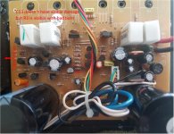
I have +/- ~65V on the output transistors and some speaker thump when I touched some of the transistor pins to take measurements.
It has 2 + and 2 - output transistors and 2 smaller balance transistors plus 1 tiny Darlington transistor between them. I removed all and they measured fine outside the circuit.(except I cant measure the Darlington really)
There are 2 driver transistors, one was removed and measured fine.
I got weird measurements for all transistors in circuit but I assume that is heavily impacted by the other components on the board. Some of transistor measurements on diode setting took 3-5 seconds to ramp up to OL from ~1.5V when in circuit but were fine when removed from circuit.
I do not have schematics for the fb210(cant fine them) but do have them for the fb212, which is the bigger brother.
I have not removed the separate input/filter board because its glued to a foam surround.
There is a 6 pin connector between the input and amp boards. The 212 spec says the pins are SG, GND, +15V, GND, -15V, CONT. I measured good grounds and +/-12V on power pins(probably right but I dont have the fb210 spec) Also 10V on CONT and small mV on SG but I may have those 2 backwards.
I'm sure this isnt the best way to report all this ... hopefully someone can help tell me what I need to look at.
I have a monitor audio FB-210 subwoofer that doesn't seem to pass input signals.
With it all connected with the cables I've been using with my current sub, the sub recognizes and wakes up to a signal(led changes from red to green when signal is delivered).
It makes a little thump when powered on or off with the switch. I get a very very soft thump when the volume knob is all the way up and turned back and forth a bit. That Is louder when the frequency cutoff is all the way to the high side. Also a super soft hum when the input rca has only the center pin inserted part way.
When rca is plugged in and I touch the other side of the cable , I get no sound unlike my old sub.
I have +/- ~65V on the output transistors and some speaker thump when I touched some of the transistor pins to take measurements.
It has 2 + and 2 - output transistors and 2 smaller balance transistors plus 1 tiny Darlington transistor between them. I removed all and they measured fine outside the circuit.(except I cant measure the Darlington really)
There are 2 driver transistors, one was removed and measured fine.
I got weird measurements for all transistors in circuit but I assume that is heavily impacted by the other components on the board. Some of transistor measurements on diode setting took 3-5 seconds to ramp up to OL from ~1.5V when in circuit but were fine when removed from circuit.
I do not have schematics for the fb210(cant fine them) but do have them for the fb212, which is the bigger brother.
I have not removed the separate input/filter board because its glued to a foam surround.
There is a 6 pin connector between the input and amp boards. The 212 spec says the pins are SG, GND, +15V, GND, -15V, CONT. I measured good grounds and +/-12V on power pins(probably right but I dont have the fb210 spec) Also 10V on CONT and small mV on SG but I may have those 2 backwards.
I'm sure this isnt the best way to report all this ... hopefully someone can help tell me what I need to look at.
No thoughts on this? I simply dont know enough to know where to start. Was hoping someone ran across something similar or could give some starting advice. Worked fine a few years ago. Boards look fine, caps look fine. I measured all the caps I could on the input board. Need to find a multimeter with high cap reading since mine tops at 32uF.
I took some board pics. If those are needed I can get them hosted somewhere.
I took some board pics. If those are needed I can get them hosted somewhere.
Try to measure for DC at speaker driver terminals. If You don't get any reading, perhaps there is some speaker protection relay kicking in. Measure again before the relay.
Have exact issue as well
So, i assume from your non response that you haven’t found resolution to pass thru issue. I have the same issue but cant determine which board might be the problem if at all.
So, i assume from your non response that you haven’t found resolution to pass thru issue. I have the same issue but cant determine which board might be the problem if at all.
I fixed mine
My MA FB210 was having a similar problem. And I have fixed it.
I noticed the problem about 2 and half years ago. Switching the off-auto-on switch to on would turn the led green but no sound.
The strange thing was I could make the sub to work by pulling the power cord out slightly and pushing it right back in quickly when the switch was in on position. It might take several tries, but it always worked. I knew it worked because I could hear the sub powered up with a pop then it functioned normally. It worked fine as long as the switch was in on position.
The trouble was the sub would stop working by itself at random – no sound again although the led was still green.
The following is the repair detail.
I cannot find FB210’s schematic but I find some diagrams for Apex Senior Sub Amp that is very close to my FB210: The Apex Junior Subwoofer Amp.
I learned the sub never powers off. What the off-auto-on switch does is changing the signal (CONT) sent to the protection circuit. The off position makes the protection engaged by connecting the CONT signal to the ground while the on position disengages the protection by connecting the CONT signal to some high (~10v) voltage. The auto position makes the CONT signal sensitive to the line audio input and holds the CONT signal high for a while after the line audio signal is off. The led related to the off-auto-on switch shows the CONT signal status only.
My problem is the protection was always engaged so the power amplifier part was shut off. The protection circuit was engaged even when the CONT signal was high (off-auto-on switch in on position) except it could be disengaged with unplugging/plugging the power cord quickly.
The culprit is the C13. It could be that the cap is near the transformer so it’s impacted by the heat. Anyways the protection circuit works and the sub functions normally again after I replaced the C13. Sorry that I don’t know why unplugging/plugging the power cord could disengage the protection with a bad C13.
My guess is if you can make your FB210 work by quickly disconnecting/connecting the power cord then you probably have a same failed C13 as I did. But even if unplugging/plugging the power cord quickly can make your FB210 work, you may still want to replace the C13.
This is because my 2nd finding: the R3. When the sub is active with either the switch in auto or on position, it means the protection circuit is disengaged, there is ~130v (positive ~68v + negative ~68v – ZD1’s ~5.6v) applied to the R3. Here is the calculation: 130x130/22k (R3 is a 22k resistor) = 768 (mw). That is a terrible big consumption for a 1/8w resistor. As a matter of fact, the PCB under the R3 shows burning sing and the soldering is de-soldering. I believe putting the switch in on position all the time makes the R3 burning a lot more than put it in the auto position. I also believe that if the R3 gets totally de-soldered and disconnected from the circuit, the protection will engage all the time. In this case, unplugging/plugging power cord won’t work and a good or bad C13 is irrelevant.
I replaced the 22k with 40k (4 x 10k 1/4w since I don’t have the right resistor) to reduce the power consumption and the sub works fine after the change.
Hopefully, your FB210 problem is either the C13 or R3 and you know now how to fix it.
If you are going to fix your FB210, make sure to properly discharge the circuit before you start to work to avoid a shock and/or some damage.
Attachments
Oh that is excellent news. I will go back to this and see if this helps. I had a bad email misspelling in my account so I never got notices about this!
I did notice some action after the plug trick. However my volume knob seems to not pass the input, or not much, and then step change at the very end right at full volume mark. I suppose a bad pot on volume could be possible.
My suggestion is to measure the voltage cross the R3. It should have 0 or near 0v when the off-auto-on led is red and around 130v when green. If this is the case, your protection circuit is working and you should hear some loud noise when touch the SG with your finger. We need to find the problem is in the pre-amp, amp, or protection part first.
To me, a bad pod is unlikely as it's not been changed much in a SW.
To me, a bad pod is unlikely as it's not been changed much in a SW.
I guess I forgot to post after typing this the first time. Volume pot was dual output but top stack was all on the ground path on the board. That measured fine off the board. The lower pot measured weird right at the end of volume stroke it jumped up to mega ohms(spec is 20k).
I clipped off the legs for the lower, bent the top pot to fit where the lower used to and soldered it back in.
Works as it should now!
I clipped off the legs for the lower, bent the top pot to fit where the lower used to and soldered it back in.
Works as it should now!
It's wonderful you figured out the top stack pot is not used and used it to replace the lower stack one. I didn't see the pod is actually a dual until you describe how you fixed yours.
Great job!
Great job!
Well ... necessity is the mother of invention .... or impatience is.
I could not find the exact, dual output pot with right angle legs at all anyway sadly.
I could not find the exact, dual output pot with right angle legs at all anyway sadly.
Too bad my next fix is a denon 4520 reciver which has done some very strangle things recently. I'm not scared of receivers but this one is something else inside.
Only thing that I may be for a little help is to tell you how to get a service manual which you probably have got one already.Too bad my next fix is a denon 4520 reciver
Good luck and tell me what it's the problem and how do you repair it after you fix it if you'd like to.
Fixed. So the receiver worked when I got it but had occasional noise and then would dc protect sometimes after awhile. Took it all out and opened it, super dirty, blew it all out and then hooked it back. Then I turned it on a day later and had no sound output period. I unplugged everything and just left it turned on on a counter ... Then sizzle and the display flickered and went dead. Still powered on and had osd and menus. Color me confused. Checked fuses I could see. Referred back to the power board schematic since I had like 50v ac or something out of that board. Found another fuse right by the mains and it was bad. Replaced that and it all works perfect for a week even left on playing all night.
I guess that fuse partially blew but not entirely? No idea but I'm happy.
I guess that fuse partially blew but not entirely? No idea but I'm happy.
That kind problem is difficult to pinpoint, I guess. I'd be happy as well if I were you. 4520 is a very good AVR. Congratulations!
- Home
- Amplifiers
- Solid State
- Monitor audio subwoofer amp issue- no input pass through