For the MA ASW100 SUB I need a schematics or service manual for possible repairs and maintenance in the future. The device is old, and malfunctions are possible. Without a schematics, it would be difficult for me to fix it if needed.
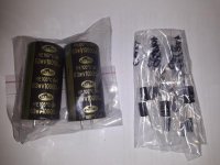
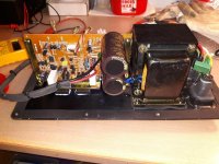
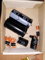
Bought used for my sister. Refresh was done by replacing all electrolytic capacitors, replacing thermal paste, and some damping material was added to the box. Removed bipolar electrolytic capacitors 150uF 100V (first order high pass filter for satellites), jumpers were installed. All small capacitors were in poor condition, increased ESR, some deviate a lot from the rated capacity. The big ones are still good.
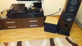
Now it sounds much better than the original. Much has been gained on the naturalness of low frequencies. The bass is no longer just a boom-boom, it has a nice rounded character and sounds more natural. It is used in one modest 2+1 system, with Wharfedale Diamond 11.1 modified minimonitors.
Bought used for my sister. Refresh was done by replacing all electrolytic capacitors, replacing thermal paste, and some damping material was added to the box. Removed bipolar electrolytic capacitors 150uF 100V (first order high pass filter for satellites), jumpers were installed. All small capacitors were in poor condition, increased ESR, some deviate a lot from the rated capacity. The big ones are still good.
Now it sounds much better than the original. Much has been gained on the naturalness of low frequencies. The bass is no longer just a boom-boom, it has a nice rounded character and sounds more natural. It is used in one modest 2+1 system, with Wharfedale Diamond 11.1 modified minimonitors.
Attachments
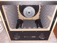

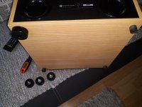
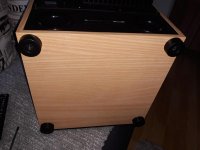
The addition of dampling material will help with the boxy sound and make the lower frequencies sound more pleasant.
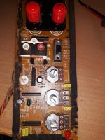
There do not apear to be schematics available but as it is only a simple amplifier, probably no consequence.
Increasing the value of the main smoothing capacitors is never a good thing, it may stress the power transformer/bridge rectifier in time.
There do not apear to be schematics available but as it is only a simple amplifier, probably no consequence.
Increasing the value of the main smoothing capacitors is never a good thing, it may stress the power transformer/bridge rectifier in time.
Damping helped, but so did the rest. First I put damping and then I listened, the difference is there, but the replacement of the capacitors is the next step upwards. SUB is constantly ON, it does not turn off the power but goes into STANDBY mode after a while, so increasing the capacitors (2x6800uF to 2x10000uF) in the power supply will not do any damage, especially not on the transformer.
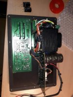
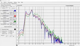
The amplifier is very classic, but the rest is much more complicated, so I would like to have a schematics. Maybe I could improve something. Let's say the cutting frequency setting is weird. Measured with 40Hz, 80Hz and 120Hz settings. This shouldn't look like this.
The amplifier is very classic, but the rest is much more complicated, so I would like to have a schematics. Maybe I could improve something. Let's say the cutting frequency setting is weird. Measured with 40Hz, 80Hz and 120Hz settings. This shouldn't look like this.
Attachments
Last edited: