I understand you have your set of priorities like anyone else. I missed the window to assemble the Mod 86, so it gets a backseat.
Oh, so you haven't actually assembled it yet?
How can you say anything about its performance (be it measured or perceived sound quality) if you haven't assembled it?
~Tom
Yes for some reason they actually developed speaker cables, which I did not feel was the best approach. But the report talked about interconnects. I have shown measurements of some interconnects I have sitting around (not individually labeled). The impedance is not flat. So for most people using unbalanced input configuration, it is not a good idea to have flat inputs.
If posting the report is allowed here, please let a moderator say so. Otherwise, people whom are interested can PM me. It should be easy for me to find it.
A report from a company who is trying to sell boutique components is unlikely to contain anything particularly useful. Might as well argue that golden ratios should be used in PCB layouts because cardas use that in their cables.
As the Mod-86 has a balanced input really not sure what your point is on impedance, even if it had a shred of applicability to audio.
There are two things to consider:A report from a company who is trying to sell boutique components is unlikely to contain anything particularly useful. Might as well argue that golden ratios should be used in PCB layouts because cardas use that in their cables.
As the Mod-86 has a balanced input really not sure what your point is on impedance, even if it had a shred of applicability to audio.
1. Using the optional unbalanced connection as mentioned.
2. When the impedance curves of both lines of the balanced input to ground mismatch somewhere over the spectrum.
I think it is reasonable to look at these.
You know, regardless who published what report, I have no prejudice against them. I just look at it objectively.
I am asking for information while looking at the design and layout. The more convincing the information, the more incentive to assemble it earlier. I worked quite quickly on the MyRef because there was some information that looked interesting enough. I have some kits that have been there for a real long time... a few years maybe?Oh, so you haven't actually assembled it yet?
How can you say anything about its performance (be it measured or perceived sound quality) if you haven't assembled it?
~Tom
Last edited:
There are two things to consider:
1. Using the optional unbalanced connection as mentioned.
2. When the impedance curves of both lines of the balanced input to ground mismatch somewhere over the spectrum.
I think it is reasonable to look at these.
The balanced input will have a 48 kΩ input impedance. The common-mode impedance is 10 MΩ at 60 Hz and 3.2 MΩ at 20 kHz. The impedance seen by a single ended source will be 48 kΩ || 10 MΩ = 47.8 kΩ at 60 Hz and 48 kΩ || 3.2 MΩ = 47.3 kΩ at 20 kHz.
You can figure out the interpolation between these two points using the method I provided in Post #1048.
~Tom
Point measurements and full spectrum measurements may not be the same. I consider full spectrum measurements more reliable. Same with damping.
Soong, the links you posted to Mauro's thread simply show a naive & tortured route that finally realises a method of measuring Zo that is IDENTICAL to how Tom's AP does it (and is recommended in all modern text books too)
From looking at many pages near those links, it appears Tom's measurements show that his Zo is exemplary .. at least according to the posters in your links.
What I haven't found is what YOU think about these measurements and sims and what conclusions & criticisms you draw ... apart from some vague statements that they don't meet your (unspecified) requirements.
You'll excuse me if I don't read all 4,500 odd posts to find your contributions in the perhaps vain hope that they may add something useful.
However, if you link to YOUR contributions, I'm sure many here will be interested.
_______________
Again, how is this sub 0R1 Zo sh*t relevant to your current drive active speakers?
And presumably, your own stuff has inputs (balance? unbalanced?) that meet some unspecified criteria that you can't describe to us unwashed masses.
_______________
To see its importance, just look at the impedance curve. If there is a 66R peak at resonance on a unit with voice coil DC 6R, the 'back EMF' is
66-6=60, ie 10x the voltage generated by the current through the coil's DC resistance.
It is an integral part of a MC speakers response. That's why you can DESIGN such a speaker to have a specified LF response. That's what da Thiele/Small BS is all about. The required 'control' of the cone is done by using the 'back EMF' and the current it generates in the Lo Zo of a voltage amp.
To talk about 'back EMF' being EVIL etc is absolute liquid BS. It's like criticising resistors for resisting the flow of electrons 😱 (... or not understanding how to interpolate between point measurements of a balance input stage to get a MORE accurate idea of the impedance with frequency 🙂 )
When you current drive a speaker, you lose this serendipitous ability to design something so it behaves consistently. You have to fudge the design by mechanical means, most of which introduce really yucky stuff. (I describe one of the few methods to do this without yuckiness in the Current Drive thread)
That's not to say there are no advantages to current drive .. but it comes with BIG caveats. eg you lose 'control' of the cone which now has to be provided by other (possibly yucky) means.
From looking at many pages near those links, it appears Tom's measurements show that his Zo is exemplary .. at least according to the posters in your links.
What I haven't found is what YOU think about these measurements and sims and what conclusions & criticisms you draw ... apart from some vague statements that they don't meet your (unspecified) requirements.
You'll excuse me if I don't read all 4,500 odd posts to find your contributions in the perhaps vain hope that they may add something useful.
However, if you link to YOUR contributions, I'm sure many here will be interested.
_______________
Again, how is this sub 0R1 Zo sh*t relevant to your current drive active speakers?
And presumably, your own stuff has inputs (balance? unbalanced?) that meet some unspecified criteria that you can't describe to us unwashed masses.
_______________
A speakers 'Back EMF' is a direct measure of cone velocity.Hydrogen Alex said:Can you or someone else with the knowledge, please explain about real world back electro magnetic force and how it does or does not affect control of the loudspeaker cones in an active amplifier system ie no passive crossover?
To see its importance, just look at the impedance curve. If there is a 66R peak at resonance on a unit with voice coil DC 6R, the 'back EMF' is
66-6=60, ie 10x the voltage generated by the current through the coil's DC resistance.
It is an integral part of a MC speakers response. That's why you can DESIGN such a speaker to have a specified LF response. That's what da Thiele/Small BS is all about. The required 'control' of the cone is done by using the 'back EMF' and the current it generates in the Lo Zo of a voltage amp.
To talk about 'back EMF' being EVIL etc is absolute liquid BS. It's like criticising resistors for resisting the flow of electrons 😱 (... or not understanding how to interpolate between point measurements of a balance input stage to get a MORE accurate idea of the impedance with frequency 🙂 )
When you current drive a speaker, you lose this serendipitous ability to design something so it behaves consistently. You have to fudge the design by mechanical means, most of which introduce really yucky stuff. (I describe one of the few methods to do this without yuckiness in the Current Drive thread)
That's not to say there are no advantages to current drive .. but it comes with BIG caveats. eg you lose 'control' of the cone which now has to be provided by other (possibly yucky) means.
Last edited:
The 1/f noise in the Parallel-86 is slightly higher. Still -120 dBV (20 Hz), -137 dBV floor is very, very quiet for a power amp.
-120 dBV is 1 uV.
-137 dBV is 141 nV.
What bandwidth?
krglee
Hi krglee,
Way back in '81 I camped and had a few cold ones at the Lions Den Hotel near Cooktown.
Is it still there?
Ah... the good ol' days....
tim
Hi krglee,
Way back in '81 I camped and had a few cold ones at the Lions Den Hotel near Cooktown.
Is it still there?
Ah... the good ol' days....
tim
kgrlee, If you have any questions regarding my posts in the MyRef thread, may I suggest you ask there. Basically, I just post findings as they happened. No conclusions drawn.
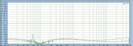
Here is an example of what can happen if you only consider point data.
As shown in the green curve of the attached file, my measured data of the XL280 which was built from a kit. The bass was never well defined with this amp, and as we can see, there are some problems shown in the damping data. The red curve is one of the MyRef configurations I played around with which I do not recall specifically which.
Now, from the damping specs of the XL280, can you imagine how the green curve can result?
Attachments
Last edited:
@soongsc
In short, you need as larger as you can get dumping factor (lower Zout) of amplifier, something in range >500 to get "precise and defined" low frequency (bass) sound.
In short, you need as larger as you can get dumping factor (lower Zout) of amplifier, something in range >500 to get "precise and defined" low frequency (bass) sound.
Some idea of what is actually being measured there would be good as you have SPL in the top right corner and either phase or level, so what are we actually looking at?
@soongsc
In short, you need as larger as you can get dumping factor (lower Zout) of amplifier, something in range >500 to get "precise and defined" low frequency (bass) sound.
Basically, this is somewhat correct, but just two points.
1) I like to see low Zout @ high frequencies because it is a measure of how well the feedback mechanism of the amplifier works across the audio band. However, for loudspeaker control, you get into diminishing returns quickly above damping factors > 30 or so. The reason being that the loudspeaker impedance and crossover ESR are also part of the loop.
2) For a speaker that is well designed to be voltage driven, it is true that you need a high damping factor to get "precise and defined" low end extension. However, there are situations where loudspeakers work better if they are driven by a highish Vout amplifier. For example, I have a pair of Tannoy K3838 concentrics, which have an absurdly low Qes. Connected to a low Zout amp, these speakers require a small cabinet (only 2 foot ^3), and as a result have a -3dB point well over 50 Hz. That is not very satisfactory for a 15 " driver. The only solution which works well is to place them in a larger case, 120 l. or so, and increase the Qes of the driver by increasing the Zout of the amplifier. This is not as silly as it sounds. These drivers were made in 1960, at a time when we still had to transition from tubes to solid state, and tube amps typically have highish Zout.. In other words, to get "precise and defined" low frequency sound does not so much require a high damping factor, but rather a damping factor which is exactly right for a specific driver/enclosure combination. In order to keep things simple, all modern loudspeaker manufacturers I know of are designing their gear for low Zout operation.
Explanation is here, which I posted a few pages back.Some idea of what is actually being measured there would be good as you have SPL in the top right corner and either phase or level, so what are we actually looking at?
http://www.diyaudio.com/forums/chip-amps/54571-my-audiophile-lm3886-approach-332.html#post2819906
I think we need to consider the overal spectrum under some realistic loading conditions. The Hafler XL280 has specs for three frequency ranges. Each range relates with what you can expect when listening of your speakers are good. The way speaker drivers damp are shown in CSD plots.@soongsc
In short, you need as larger as you can get dumping factor (lower Zout) of amplifier, something in range >500 to get "precise and defined" low frequency (bass) sound.
I can see no explanation of what that is a graph of and how it was measured. Just lots of graphs with no coherent attempt at analysis.
Here is an example of what can happen if you only consider point data.
As shown in the green curve of the attached file, my measured data of the XL280 which was built from a kit. The bass was never well defined with this amp, and as we can see, there are some problems shown in the damping data.
The only thing your plot shows is that you have an issue with mains hum in your setup. That's why you get the peak at 60 Hz and crud at 120, 180, 240, ... Hz. The ringing before and after the 60 Hz peak looks like an artifact of the sampling, either a pre/post IIR filter response or sampling window response.
You used this measurement of mains hum to support your perception of the bass not being well-defined (which may/may not be an accurate perception). This is experimenter bias and/or confirmation bias.
For the measurement to show anything meaningful, you need to remove the ground loop from the system and remeasure. With the interest gathered here, I'm sure you will be able to attract quite a few people to help with the debugging of your setup if you start a new thread, for example, in the test & measurement forum. I'll be happy to participate there to the extent my time allows.
~Tom
The way it is measured is explained in the link I provided. If it is not understandable, I don't think I could explain it better.I can see no explanation of what that is a graph of and how it was measured. Just lots of graphs with no coherent attempt at analysis.
The point is not discussion of the Hafler amp, but why I like to look at measured curves instead of point values. The Hafler amp was built from a full kit with professional document. It demonstrates anything can happen when building a kit, even with something documented like the Mod86. Hafler also provided point inspection procedures, and a difference measurement method. All parts came directly from Hafler.The only thing your plot shows is that you have an issue with mains hum in your setup. That's why you get the peak at 60 Hz and crud at 120, 180, 240, ... Hz. The ringing before and after the 60 Hz peak looks like an artifact of the sampling, either a pre/post IIR filter response or sampling window response.
You used this measurement of mains hum to support your perception of the bass not being well-defined (which may/may not be an accurate perception). This is experimenter bias and/or confirmation bias.
For the measurement to show anything meaningful, you need to remove the ground loop from the system and remeasure. With the interest gathered here, I'm sure you will be able to attract quite a few people to help with the debugging of your setup if you start a new thread, for example, in the test & measurement forum. I'll be happy to participate there to the extent my time allows.
~Tom
I am more interested in seeing what the Mod86 curve would look like.
Last edited:
I still am none the wiser to the X axis or scaling tho.
This is where I started to learn.
http://www.diyaudio.com/forums/chip-amps/54571-my-audiophile-lm3886-approach-9.html#post683346
So basically you have the same information I had when I started. Based on that, I just dug in and get my hands dirty to fully appreciate how the I formation relates with listening impression.
90db in my plots equate to 0db in his plot.
Last edited:
- Home
- Vendor's Bazaar
- Modulus-86: Composite amplifier achieving <0.0004 % THD+N.