All,
Its been a bit but I've still been stewing away at a few things. Due to another project of mine, I've found a decently reliable Chinese boardhouse that I'm happy with the end-result of. What that means is quick-turnaround, repeatable, decent quality PCBs.
In my thoughts of doing another amp for my living-room setup, this-time a P-P design (vs the SE for my vinyl), I was going to make some "local" PCBs to use for the component wiring. Some of you might know about Glassware's "Aikido" amp (and many others) and this would be similar to that; PCB with your choice of tube(s) that I'd document and layout some values based on "common options".
Now, before I get into anything else let me set an expectation. These aren't going to have all the bells and whistles. Hell, my SE 6l6 is something like 6 resistors and 5 capacitors (outside of the PSU); for something thats "simple" and "affordable", it sounds pretty decent. So none of this will have something like Wavebourn's dynamic clipping feedback or anything like that but the goal was:
Alright, that being said, here's a sample of what I've got thusfar:
Input stage (scheme and PCB in attach)
Few things on this:
I know pt.2 and p.4 aren't ever really used (or practical) in a hifi application but just wanted to demonstrate that since these are through-hole you have pickup points that allow for a wide array of scenarios.
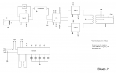
The idea is that then this "input block" would be coupled with a phase-inverter, volume, tonestack, and power supply boards, those boards would be wired together at their termination points and you'd essentially have an amp. An example of what a guitar amp would look like in terms of the "connection blocks" is also included.
I know "hand wiring" and "point to point" are the vogue thing, after doing a few though I wouldn't making my life easier and wanted to try something like this for my own edification anyway.
I've got (thsufar):
If there's some more interest in these, I can put together something about what I all have and some of the basic options. I'd primarily appreciate some Layout or Scheme feedback from some of you guys (even though its a pretty stupid simple design) in case there's something i missed or something I'm not thinking of.
Not looking at "making a profit" or "going commercial" or anything with these. The more and more I learn about tubes it just baffles me how (at their core) there's your 4-5 building blocks and that's about it; so, naturally, i thought having some of these blocks laying around for prototyping, or making an amp, would be a beneficial endeavor even if just for myself.
Lastly, (and maybe this is just me being a big softie) I learned all of this, being a relatively young guy at 29, from reading pages/posts from folks like valve-wizard, aiken, cavali, glassware, AND YOU guys, etc...So this is/was an attempt at having a "kit" for that someone who's like "i want to make my first amp, where do i start". I know there's whole kit options out there but the hope was with these you could do a PP, or an SE, or a guitar amp, or whatever the hell you want; maybe just having the tone controls all in one bunch is what you want, or its the simple PSU with multiple B+ rails.
lmk what you think, thanks
Its been a bit but I've still been stewing away at a few things. Due to another project of mine, I've found a decently reliable Chinese boardhouse that I'm happy with the end-result of. What that means is quick-turnaround, repeatable, decent quality PCBs.
In my thoughts of doing another amp for my living-room setup, this-time a P-P design (vs the SE for my vinyl), I was going to make some "local" PCBs to use for the component wiring. Some of you might know about Glassware's "Aikido" amp (and many others) and this would be similar to that; PCB with your choice of tube(s) that I'd document and layout some values based on "common options".
Now, before I get into anything else let me set an expectation. These aren't going to have all the bells and whistles. Hell, my SE 6l6 is something like 6 resistors and 5 capacitors (outside of the PSU); for something thats "simple" and "affordable", it sounds pretty decent. So none of this will have something like Wavebourn's dynamic clipping feedback or anything like that but the goal was:
- make it simple
- make it easy to learn with
- make it easy to replicate
- make it accessible
Alright, that being said, here's a sample of what I've got thusfar:
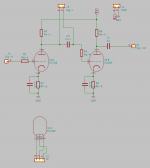
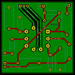
Input stage (scheme and PCB in attach)
- standard noval socket (9-pin)
- single tube, two triode stages
Few things on this:
- cathode bypass caps optional
- can include C1, but could use the-through hole for a "fat" switch wiring on V1A's (U1 on scheme) Rk, like what's in the "blues jr".
- C2 can be omitted and signal at J3 connected to a Tonestack, or volume pot, or any circuit of choice
- additionally could omit Rk&Ck and wire into a constant voltage supply of your choosing/design to provide a fixed bias.
I know pt.2 and p.4 aren't ever really used (or practical) in a hifi application but just wanted to demonstrate that since these are through-hole you have pickup points that allow for a wide array of scenarios.
The idea is that then this "input block" would be coupled with a phase-inverter, volume, tonestack, and power supply boards, those boards would be wired together at their termination points and you'd essentially have an amp. An example of what a guitar amp would look like in terms of the "connection blocks" is also included.
I know "hand wiring" and "point to point" are the vogue thing, after doing a few though I wouldn't making my life easier and wanted to try something like this for my own edification anyway.
I've got (thsufar):
- input, noval
- PI, noval
- tonestack
- volume
- L/R balance
- Output, noval
- Output, octal
- few others that are guitar specific, not somuch for hifi
If there's some more interest in these, I can put together something about what I all have and some of the basic options. I'd primarily appreciate some Layout or Scheme feedback from some of you guys (even though its a pretty stupid simple design) in case there's something i missed or something I'm not thinking of.
Not looking at "making a profit" or "going commercial" or anything with these. The more and more I learn about tubes it just baffles me how (at their core) there's your 4-5 building blocks and that's about it; so, naturally, i thought having some of these blocks laying around for prototyping, or making an amp, would be a beneficial endeavor even if just for myself.
Lastly, (and maybe this is just me being a big softie) I learned all of this, being a relatively young guy at 29, from reading pages/posts from folks like valve-wizard, aiken, cavali, glassware, AND YOU guys, etc...So this is/was an attempt at having a "kit" for that someone who's like "i want to make my first amp, where do i start". I know there's whole kit options out there but the hope was with these you could do a PP, or an SE, or a guitar amp, or whatever the hell you want; maybe just having the tone controls all in one bunch is what you want, or its the simple PSU with multiple B+ rails.
lmk what you think, thanks
Attachments
A preamp PCB is one thing. Power tube PCB is another . . .
I never liked the idea of mounting output tube sockets on a PCB.
Heat and PCB may not be a good combination.
And, those sockets can really grab the tubes, when you remove them,
you stress the PCB.
I never liked the idea of mounting output tube sockets on a PCB.
Heat and PCB may not be a good combination.
And, those sockets can really grab the tubes, when you remove them,
you stress the PCB.
A preamp PCB is one thing. Power tube PCB is another . . .
I never liked the idea of mounting output tube sockets on a PCB.
Heat and PCB may not be a good combination.
And, those sockets can really grab the tubes, when you remove them,
you stress the PCB.
While both heat and compliance/flex are considerations, I don't forsee them to be too much of an issue. In a previous job I did some hardware testing on multi-layer boards (i think 12-14 layers?) and we put those while operating in a -20*F to 120*F heat cycle. While that's different than the localized heat of a tube on a board, its also considerably more extreme and these (the tube boards) have considerably stouter pads/traces. Even at a lower manufacturing quality I don't think it should be an immediate issue.
For pressure/torque/socketing forces, I'm planning on using chassis mounted sockets to help alleviate so there's minimal forces directly on the board. I don't know of any sockets out there that have a truly rigid pin in the socket, so there will always be some wiggling. That said, I don't think it would be at the level to cause failure.
In any event, proof of concept and testing will prove both of those statements either right or wrong! lol.
How were you planning to implement the needed grid leak resistors?
My mind had been on oscillations recently so the grid stoppers were front & center but you're right, I need to add in the grid leaks as well. thanks for the reminder 😛
I've been tinkering around with the general premise and scribbling on paper so this was a first draft revision of the concept. I wanted to make sure i had the essentials without them being bloated. That said, as you pointed out, this (the leak resistors) is something that very much needs to be included.
Also apparently a mod moved it? Just to be clear, I know i used a guitar amp for an example but this wasn't specific to either (hifi or instrument). The whole thing that sparked this was for making a new P-P for the home theatre, doesn't really matter either way i guess.
I never liked the idea of mounting output tube sockets on a PCB.
I have sold over 1000 PCBs for audio amp use that have the output tube sockets directly soldered into the board. Most are class A SE which is worse case for continuous dissipation.
There have been no issues with the tubes, sockets or PCB from this. Some people (including me) have mounted power resistors (cathode bias and power supply) on the under side of the board with minimal or zero ventilation. This has caused some discoloration and minor delamination after 10+ years of use, so plan accordingly.
I have some modular amp stuff in the works already too. They won't appear until late this year, or next year. There are some more complete amp boards to come first.
Any of those happen to be with some of your franken-powered 1.21 jigawatt setups? 😀
Glad to hear someone with some more extensive testing confirms my suspicions though. I've done some fet-switches on 4oz clad in high NVH automotive applications (read, racecars) but this setup was something just different enough to give me pause.
Also, as an aside; I totally missed you in the call-outs of the OP. Not to brown-nose but your site/schematics/information are a wealth of information as well! If you're going down this route, it means I can't be too far off the mark (in concept) at least. Hit me up with a PM if you would like to use me as a guinea pig; I'm always up for something.
Any of those happen to be with some of your franken-powered 1.21 jigawatt setups?
No, these were run of the mill SSE and TSE amps stuck into too small of a box with no airflow. Mine was purpose built too small, mostly because my former work space / listening room / lab was all stuffed into a 10 X 10 foot room.
There have been a few SSE amps that went into red plate runaway from gassy output tubes. This led to overheated cathode resistors, exploded bypass caps, and crispy looking PC boards. New parts fixed the amps even with the brown spots on the board.
As an RF transmitter engineer at Motorola for 41 years, I have fried far more silicon, GaAs, Gan and SiC than tubes. We heat soaked our mobile radios at full power in 80 degrees C to simulate a cop throwing his jacket in the trunk over the radio in a black Crown Vic in the Florida summer. Yes, we fried some boards, but as with the tube amps, something else blew first.
The modular stuff is still in the breadboard stage right now, and the TSE-II redesign as well as an RF contract engineering job is keeping me busy now, so I can't even say when anything will be ready.
- Status
- Not open for further replies.
- Home
- Amplifiers
- Tubes / Valves
- Modular Tube Amp PCB thoughts