Well, I've been working on a modular DAC for quite some time now.
The project has taken many turns along the way and will surely take a few more before it is completed.
I will try to describe the project as best I can.
It started out as a modular approach (separate boards for digital reciever, D/A IC, output etc etc) with just one DAC IC in mind, the WM8740 and only the DIR9001 digital reciever.
It has since grown, alot in fact, and now I have several options for most modules to choose from when built and compared to find the to my ears best sounding combination.
On the input side I have:
DIR9001
WM8804
WM8805
I have an AD1896A should I want to try ASRC/SRC. I don't have any PCB for this, but will do my best to perf board the module
DAC IC's:
WM8740 x2 these I don't have any PCB's for, but I'm doing my best perf boarding the dual WM8740 module
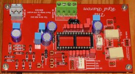
TDA1541A x3 (I have one Red Baron 5.0 populated and two more boards ordered. This DAC will use two of them in parallel)
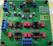
PCM1974 x3 (one on a dip adapter, one on a PCB with I2S input and one waiting for one more PCB with I2S input)
I also have a bunch of TDA1387's that I might try and design a perf board module for with 8 or so in parallel.
I do NOT yet have any USB-interface. I may or may not add that to the design. To fit the modular approach of this project, it would have to have I2S output.
For the 2x TDA1541A I'll compare to the 2x PCM1794 and 2x WM8740, I have a NPC SM5814 digital filter (thanks to my dear friend Dave for this).
I also have 2pcs Sony CXD1244, that are supposedly compatible with the TDA1541A. Though I don't have any schematic for how to wire one of these between one of the digital recievers mentioned above and the Red Baron 5.0 boards.
Below I'll try do describe my plans for the parallel Red Baron's.
Digital Reciever will be either WM8804 (bought that assembled from Tekdevice) or a perf boarded WM8805 with "off board" 0.1ppm TCXO with either a "flea" supply or another design using a 74HC04D to buffer(?) the clock output.
The digital reciever will feed into the digital filter, in this case NPC SM5814.
I only have one of these IC's unfortunatly as they seem hard to source.
The digital filter then feeds into both Red Baron boards, so not going NOS with them.
The Red Baron boards then have the outputs paralleled before I/V, which is passive this far in the planning, and then on to Mr. Borbely's Opamp 4.
The passive I/V for the parallel Red Barons consists of (per channel) a Riken RMG 22R resistor parallel with a 100nF russian NOS PIO cap.
The opamp 4 is a tube/mosfet hybrid stage.
From there the outputs will go to a pair of matched russian NOS PIO caps (2.13uF) and on the RCA outputs.
Enclosure/chassis:
I thought I would have plenty of space in the enclosure I had chosen for this build, a medium sized amplifier case. However, as things often are in DIY, what you plan for/think is often not completely as you'd thought when it's time for the real life implemantation of it all.
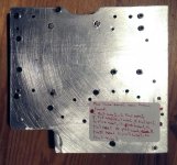
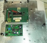
I've started to solve the space problem by using aluminium "floors", using aluminium sheets to cut out plates to mount boards on so that I can better utilize the vertical space in the enclosure.
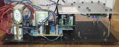
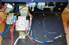
The transformers alone take up about 1/3 to 1/2 of the chassis lol.
I have the following transformers in there now:
1. 12-0-12VAC 500mA for -15Vdc (TDA1541A), +/-12Vdc (PCM1794 output should I use the onboard solution)
Should the 500mA not be sufficient, I have a 1A version of the same transformer.
2. 0-9Vac 1200mA for +3.3Vdc supplies, +5Vdc supplies (have another identical should I need it)
3. 0-6Vac 5VA for the tube filaments (2x ECC86 tubes in the Borbely circuit)
4. 24-0-24Vac 30VA for the +/-24Vdc for the mosfet part of the Borbely circuit.
Questions as of today:
What could I use as a substitute for the NPC SM5814 for my third Red Baron board?
I've seen that SM5813, SM5843 and a few others from NPC are easily available. I don't know however if they'd work or how to implement them.
Would the CXD1244 a) work as does the SM5814? and b) how would one go about implementing it between the digital reciever and the TDA1541A?
I'll conclude this first post by attaching a few pictures.
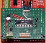
The WM8804 & SM5814 are mounted "upside-down" on the alu-plate that will have the Borbely circuit mounted on the other side. Due to limited space even on the height, The 1.5mm thick alu-plate will also be heatsink for the mosfets in the Borbely circuit.
The project has taken many turns along the way and will surely take a few more before it is completed.
I will try to describe the project as best I can.
It started out as a modular approach (separate boards for digital reciever, D/A IC, output etc etc) with just one DAC IC in mind, the WM8740 and only the DIR9001 digital reciever.
It has since grown, alot in fact, and now I have several options for most modules to choose from when built and compared to find the to my ears best sounding combination.
On the input side I have:
DIR9001
WM8804
WM8805
I have an AD1896A should I want to try ASRC/SRC. I don't have any PCB for this, but will do my best to perf board the module
DAC IC's:
WM8740 x2 these I don't have any PCB's for, but I'm doing my best perf boarding the dual WM8740 module
TDA1541A x3 (I have one Red Baron 5.0 populated and two more boards ordered. This DAC will use two of them in parallel)
PCM1974 x3 (one on a dip adapter, one on a PCB with I2S input and one waiting for one more PCB with I2S input)
I also have a bunch of TDA1387's that I might try and design a perf board module for with 8 or so in parallel.
I do NOT yet have any USB-interface. I may or may not add that to the design. To fit the modular approach of this project, it would have to have I2S output.
For the 2x TDA1541A I'll compare to the 2x PCM1794 and 2x WM8740, I have a NPC SM5814 digital filter (thanks to my dear friend Dave for this).
I also have 2pcs Sony CXD1244, that are supposedly compatible with the TDA1541A. Though I don't have any schematic for how to wire one of these between one of the digital recievers mentioned above and the Red Baron 5.0 boards.
Below I'll try do describe my plans for the parallel Red Baron's.
Digital Reciever will be either WM8804 (bought that assembled from Tekdevice) or a perf boarded WM8805 with "off board" 0.1ppm TCXO with either a "flea" supply or another design using a 74HC04D to buffer(?) the clock output.
The digital reciever will feed into the digital filter, in this case NPC SM5814.
I only have one of these IC's unfortunatly as they seem hard to source.
The digital filter then feeds into both Red Baron boards, so not going NOS with them.
The Red Baron boards then have the outputs paralleled before I/V, which is passive this far in the planning, and then on to Mr. Borbely's Opamp 4.
The passive I/V for the parallel Red Barons consists of (per channel) a Riken RMG 22R resistor parallel with a 100nF russian NOS PIO cap.
The opamp 4 is a tube/mosfet hybrid stage.
From there the outputs will go to a pair of matched russian NOS PIO caps (2.13uF) and on the RCA outputs.
Enclosure/chassis:
I thought I would have plenty of space in the enclosure I had chosen for this build, a medium sized amplifier case. However, as things often are in DIY, what you plan for/think is often not completely as you'd thought when it's time for the real life implemantation of it all.
I've started to solve the space problem by using aluminium "floors", using aluminium sheets to cut out plates to mount boards on so that I can better utilize the vertical space in the enclosure.
The transformers alone take up about 1/3 to 1/2 of the chassis lol.
I have the following transformers in there now:
1. 12-0-12VAC 500mA for -15Vdc (TDA1541A), +/-12Vdc (PCM1794 output should I use the onboard solution)
Should the 500mA not be sufficient, I have a 1A version of the same transformer.
2. 0-9Vac 1200mA for +3.3Vdc supplies, +5Vdc supplies (have another identical should I need it)
3. 0-6Vac 5VA for the tube filaments (2x ECC86 tubes in the Borbely circuit)
4. 24-0-24Vac 30VA for the +/-24Vdc for the mosfet part of the Borbely circuit.
Questions as of today:
What could I use as a substitute for the NPC SM5814 for my third Red Baron board?
I've seen that SM5813, SM5843 and a few others from NPC are easily available. I don't know however if they'd work or how to implement them.
Would the CXD1244 a) work as does the SM5814? and b) how would one go about implementing it between the digital reciever and the TDA1541A?
I'll conclude this first post by attaching a few pictures.
The WM8804 & SM5814 are mounted "upside-down" on the alu-plate that will have the Borbely circuit mounted on the other side. Due to limited space even on the height, The 1.5mm thick alu-plate will also be heatsink for the mosfets in the Borbely circuit.
Attachments
-
 Red_Baron_populating_12.jpg180.1 KB · Views: 619
 -
 PCM1794_board_populating_33.jpg128.3 KB · Views: 150
 -
 WM8805_mkII_populating_34.jpg191.9 KB · Views: 111
 -
 WM8805_mkII_populating_25.jpg160 KB · Views: 145
 -
 SM5814_board_populating_13.jpg306.3 KB · Views: 617
 -
 IMG_20160106_181153.jpg494.2 KB · Views: 612
 -
 Parallel_TDA1541A_IV_stage_4.jpg56.4 KB · Views: 603
 -
 Red_Baron_populating_14.jpg118.9 KB · Views: 595
 -
 Enclosure_populating_66.jpg142.3 KB · Views: 164
 -
 Enclosure_populating_61.jpg107.1 KB · Views: 126
Small update.
I've been doing mock-up layouts etc mostly as I'm waiting for parts.
Hopefully I'll get more parts this week.
I've got more Alu-sheets on the way as well. They really come in handy when space is tight.
Plus, I'm getting atleast halfway decent with the dremel and cutting disc lol
I am trying to keep the transformers as far away from the signal electronics as possible.
Attachments
Almost forgot to update this thread.
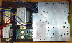
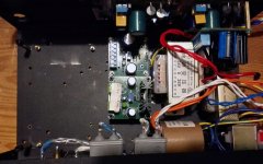
I've made some changes to the layout in the chassis to accomodate more vregs, I've also swapped the 12-0-12 EI 500mA for a 30VA 0-15 0-15VAC R-core.
I've added two LT1083 regs, almost finished the two PCM1794 PCB's (waiting for more DIP8 sockets and some 1206 300R resistors)
I'll get all parts needed (I hope) to complete the Borbely tube/mosfet hybrid output.
In the pics the I/V is the one for a single Red Baron and the layout is a mock-up. The paper on the perf board will probably be removed once the board is done. I'm leaning towards using the 1.5mm alu-sheet as heatsink for the mosfets. I'm also considering re-building the output circuit on a smaller perf board as the tubes no longer will be fitted in the female pinheader on the board.
I've completed the two passive I/V boards (one for a single Red Baron board and one for two parallel Red Baron boards)
I've gotten some more vregs to try out, MIC5205-5.0, MIC5205-3.3 and LP2989IM-3.3
In addition I have two more LT1083 boards, either for single positive or for dual rail used with the R-Core transformer, a perf board dual rail LT1083 board, a few LM317 boards, a few LM337 boards and a few LM317+LM337 boards.
My goal is to give each consumer it's own voltage reg, that might not be practical considering space available.
WM8805, I think I'll re-work that board a bit using LDO regs close to the IC instead of using off board regs with wiring going to the WM8805 board.
I don't know if something like MIC5205-3.3 or LP2989IM-3.3 close to the IC is preferable to LT1083/LM317 with wiring going to the board?
There will still be regs dropping the voltage to +5Vdc that'll be fed to the WM8805 board where LDO's will drop it to +3.3Vdc.
The 12Mhz TCXO will be on a separate board, either Flea or buffered (74HC04D).
I do have the WM8804 board that I'll use either permanently if it sounds better or until the WM8805 is completed and no more re-working is needed.
Transformers are now:
30VA 0-15vac 0-15vac
30VA 24-0-24vac
0-9vac 1200mA
0-6vac 5VA
Sorry about the bad phone pics. I'm often too tired/lazy to get out the DSLR when done for the day.
Attachments
-
 Enclosure_populating_98.jpg134.3 KB · Views: 56
 -
 Enclosure_populating_99.jpg119.1 KB · Views: 68
 -
 Enclosure_populating_95.jpg189.3 KB · Views: 105
 -
 PCM1794_board_2_populating_1.jpg138.7 KB · Views: 75
 -
 PCM1794_board_2_populating_2.jpg63.4 KB · Views: 107
 -
 Borb_populating_82.jpg150 KB · Views: 108
 -
 Borb_populating_87.jpg111.1 KB · Views: 74
 -
 Parallel_TDA1541A_IV_stage_mkII_2.jpg191.4 KB · Views: 74
 -
 Parallel_TDA1541A_IV_stage_mkII_1.jpg62.4 KB · Views: 62
Small update again.
I'll probable move the WM8804 and SM5814 boards to the front panel(or preferably, if space allows, to the back panel).
the alu-sheet they are mounted on now will get a bit toasty as it will act as heatsink for the mosfets.
Finally got the parts needed to complete the tube/mosfet hybrid output.
I was only missing RN60D 100K and RN60D 47R5 (both by IRC).
Parts used are:
Allen Bradley resistors, IRC RN60D resistors, TSC polystyrene caps, FSC polystyrene caps.
Did get a little work done on the tube board yesterday.
I've also recieved the parts to populate the two Red Barons I ordered in the latest run of the group buy. Making for a total of 3 Red Baron boards, though only two will be used in this DAC.
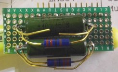
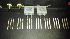
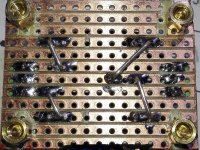
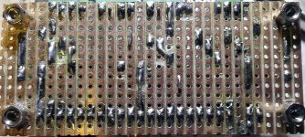
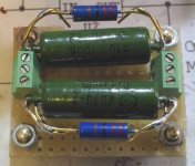
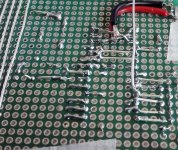
I re-built the I/V for parallel Red Baron boards.
Same parts, but a smaller board.
Riken RMG 22R resistors
Russian NOS PIO's 100nF
Wiring used "on board" is 0.9mm tinned copper wire. Nice to work with and the largest diameter that fits perf board holes.
Leads kept long on the Riken's in case I at some point need them for something else or find that 22R is not the best value for I/V resistor for parallel TDA1541A's.
I'll probable move the WM8804 and SM5814 boards to the front panel(or preferably, if space allows, to the back panel).
the alu-sheet they are mounted on now will get a bit toasty as it will act as heatsink for the mosfets.
Finally got the parts needed to complete the tube/mosfet hybrid output.
I was only missing RN60D 100K and RN60D 47R5 (both by IRC).
Parts used are:
Allen Bradley resistors, IRC RN60D resistors, TSC polystyrene caps, FSC polystyrene caps.
Did get a little work done on the tube board yesterday.
I've also recieved the parts to populate the two Red Barons I ordered in the latest run of the group buy. Making for a total of 3 Red Baron boards, though only two will be used in this DAC.
I re-built the I/V for parallel Red Baron boards.
Same parts, but a smaller board.
Riken RMG 22R resistors
Russian NOS PIO's 100nF
Wiring used "on board" is 0.9mm tinned copper wire. Nice to work with and the largest diameter that fits perf board holes.
Leads kept long on the Riken's in case I at some point need them for something else or find that 22R is not the best value for I/V resistor for parallel TDA1541A's.
Attachments
Small update again.
I haven't had much time for DIY, so not too much has gotten done.
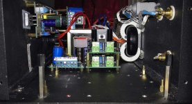
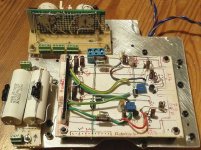
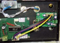
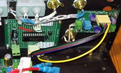
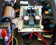
I did mount the WM8804 and SM5814 on the backpanel
I also temporarily removed the 0-9VAC 1.2A EI as I think the 30VA 0-15vac 0-15vac R-Core might be enough to handle everything except the Borbely circuit.
By using the LT1083CP boards to do rectifying and set them to +/-15Vdc and then put the LM317/337 regs after them.
My thinking is that the LT1083's can handle quite a bit of current, making them close to ideal to feed the following vregs.
In the pic, I made a mistake, the +3.3Vdc will not be taken from the reg for the SM5814, but from the second +5Vdc for one of the Red Baron boards.
I haven't had much time for DIY, so not too much has gotten done.
I did mount the WM8804 and SM5814 on the backpanel
I also temporarily removed the 0-9VAC 1.2A EI as I think the 30VA 0-15vac 0-15vac R-Core might be enough to handle everything except the Borbely circuit.
By using the LT1083CP boards to do rectifying and set them to +/-15Vdc and then put the LM317/337 regs after them.
My thinking is that the LT1083's can handle quite a bit of current, making them close to ideal to feed the following vregs.
In the pic, I made a mistake, the +3.3Vdc will not be taken from the reg for the SM5814, but from the second +5Vdc for one of the Red Baron boards.
Attachments
Last edited:
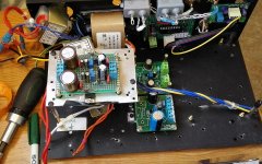
Haven't gotten very much done on the DAC, but I did put together a perf board LM317/337 vreg.
My biggest issue atm is fitting all voltage regulators etc I want in the enclosure.
I took some, again...I'm sorry, bad cell phone pics of the enclosure etc today.
One of the LT1083's came a bit close to the alu-sheet/voltage reg heatsink.
For now I just put some electrical tape(correct english term?) to make sure there will be no shorts.
This project seems to be constantly waiting for some small part to arrive before it can move along.
This is my bad as I keep changing things.
I don't have any timelimit for the project...but it'd better sound good when done lol
Attachments

Small update.
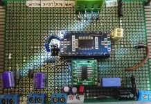
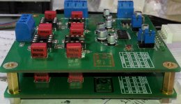
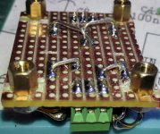
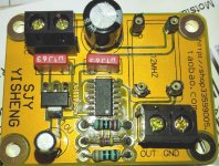
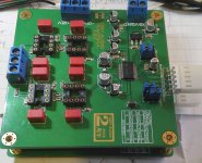
I recieved one of the TCXO options for the WM8805 board (still not quite done).
I also populated the PCB as I had some time over.
The other option is a Flea PCB that I'm waiting for.
I see that I missed to clean some solder paste, good thing I take alot of pictures lol
I recieved one of the TCXO options for the WM8805 board (still not quite done).
I also populated the PCB as I had some time over.
The other option is a Flea PCB that I'm waiting for.
I see that I missed to clean some solder paste, good thing I take alot of pictures lol
Attachments
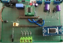
Recieved the Flea PCB as well but haven't started populating it yet.
Tested the perf board WM8805 as far as powering on without the IC in the socket.
So far so good.
As a smałl side project, I started a NOS 4x TDA1387 parallel DAC as well.
I'm also looking at getting Sony CDX1244, WM8804/05 and TDA1541A playing nicely together.
There are other filters/OS available (SM5814 that I know works) that could with the TDA1541A.
NPC SM5813, SM5843 etc are some that are readily available as opposed to the SM5814.
Unfortunately I'm not yet read up on digital circuits (yet) enough to know which ones that does work and sound good.
SAA7220P/B is out, I don't like it. I have a couple though, removed from CD-players.
One day soon I hope I'll have the time to get my perf board AD1896A populated and working too.
Alot of builds going on at once, I know.
Any tips about digital filters with OS that works with TDA1541A?
SAA7220's main problem is its power draw, it tends to dirty up its supplies so needs its own dedicated regulator.
Yes, but I'd like to find another IC that works, I know some(one) have had success with CXD1244.
You could consider programming an FIR filter yourself into an ARM CPU. I extracted the coefficients from my SAA7220 and incorporated them into a filter based on an NXP LPC1313 CPU. It took about 5% of the power of the SAA7220.
Wow, that would mean learning programming and some hw to make it possible as well I suppose.
Re-working the dual WM8740 board btw. I didn't like how messy it got.
I started taping printer paper to the perf boards, being able to draw on that makes the layout process so much easier.
And no harm in leaving the paper when done either.
Almost forgot, I ordered a 22.5792Mhz TCXO for the AD1896A.
I'm planning on using that with a "Flea" board.
So for that DAC the chain would be, WM8805 - AD1896A-dual WM8740-whatever buffer/filter/trafo I end up using.
I don't know how using two good TCXO's (12Mhz wm8805 & 22.5792Mhz AD1896A) will effect the final result, I doubt it'll be negative though.
I'm planning on using that with a "Flea" board.
So for that DAC the chain would be, WM8805 - AD1896A-dual WM8740-whatever buffer/filter/trafo I end up using.
I don't know how using two good TCXO's (12Mhz wm8805 & 22.5792Mhz AD1896A) will effect the final result, I doubt it'll be negative though.
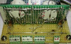
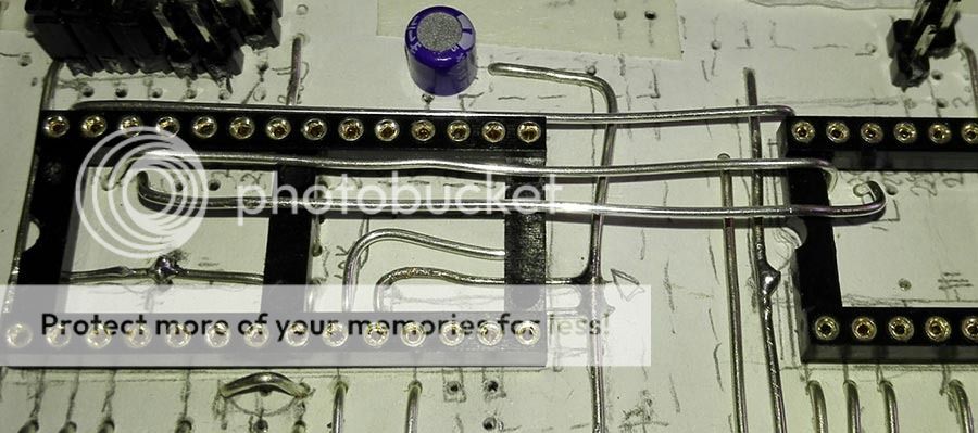
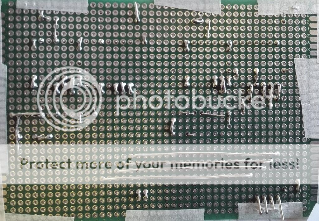
About halfway done with the WM8740 board.
It's alot easier work with the paper on the perf board, allowing me to wire (using 0.9mm tinned Cu "fuse wire") on both sides of the plated through double sided board without unwanted connections aka shorts.
SMD's are soldered on the bottom side where there's no paper.
Still undecided on the output, ie what I'll put after the dual WM8740's.
I have a huge number of BJT's, some fet's, a variety of opamps and two edcor transformers (XSM 600:600 and 10K:10K).
This project will likely end up with two DAC's that I keep.
TDA1541A x2 parallel and dual WM8740 or dual PCM1794.
All depending on what sounds better to me in my system.
The main system is about to be revived as well, with 2x TA2022 in BTL for the woofers and one in stereo for mids and highs.
I have the analog metric TDA1541A dac there now with a tube jfet SSRP hybrid output.
Most likely the Red Baron and whatever else I combine it with will beat that DAC.
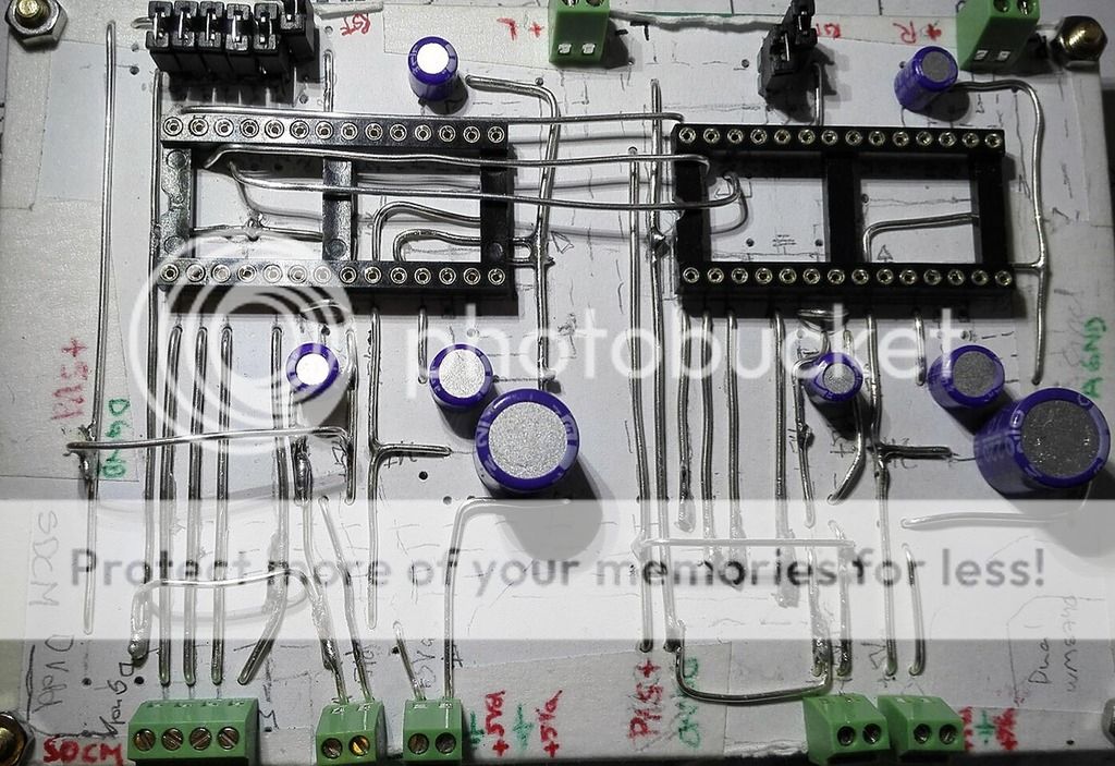
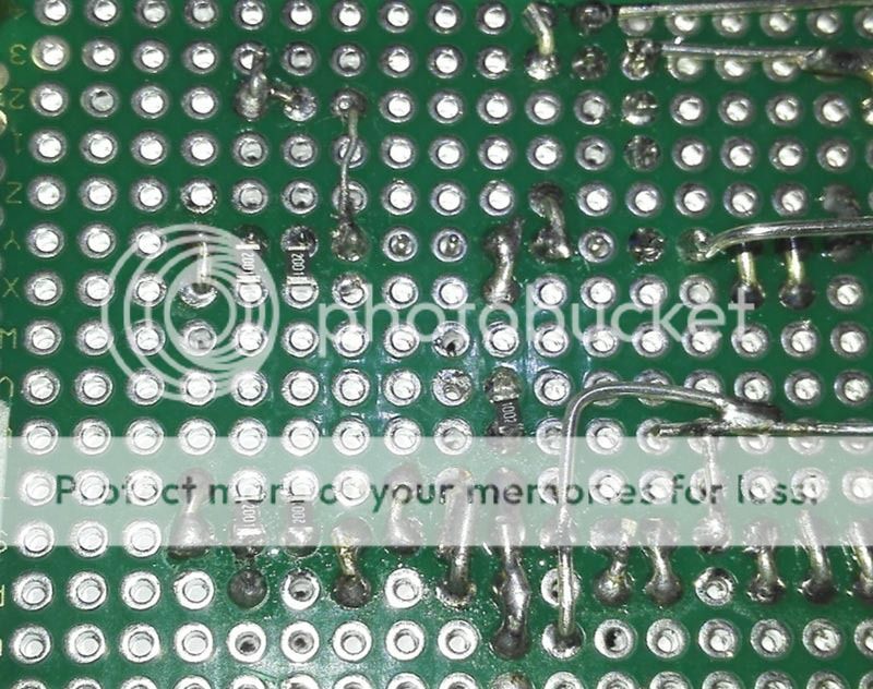
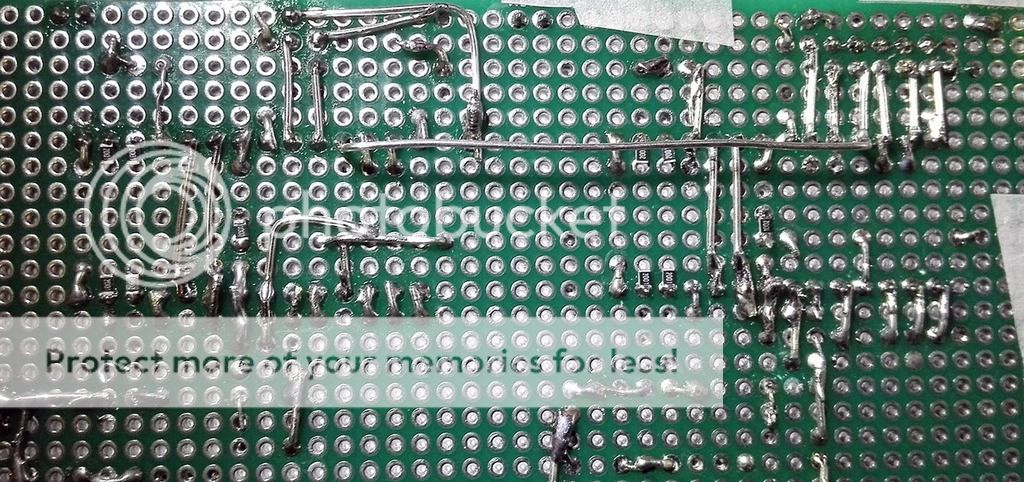
Small update.
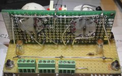
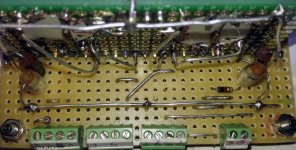
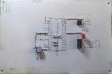
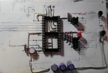
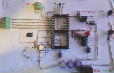
It may not be very pretty to look at, but all connections are where they should.
There's still a little bit left to do, wire the 2K resistors to outputs etc and cleaning up the board when all soldering is done.
There are four supplies, one digital and one analog for each channel.
Analog and digital gnd's are kept separate.
Pics aren't very good since I'm still to lazy/tired to take out my DSLR...
That's all for today, now it's time to eat some good food and relax with my fiance.
It may not be very pretty to look at, but all connections are where they should.
There's still a little bit left to do, wire the 2K resistors to outputs etc and cleaning up the board when all soldering is done.
There are four supplies, one digital and one analog for each channel.
Analog and digital gnd's are kept separate.
An externally hosted image should be here but it was not working when we last tested it.
Pics aren't very good since I'm still to lazy/tired to take out my DSLR...
An externally hosted image should be here but it was not working when we last tested it.
An externally hosted image should be here but it was not working when we last tested it.
An externally hosted image should be here but it was not working when we last tested it.

That's all for today, now it's time to eat some good food and relax with my fiance.
Small update again.
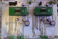
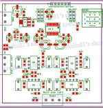
I've started layout and populating of the AD1896A ASRC board.
The plan (and reason for using 8x12cm perf boards all around) is to stack the WM8805, AD1896A and WM8740 board on top of eachother.
Since the boards aren't that tall populated, this way the footprint will be small and the height of the thing won't be too much of an issue either.
The paper layout method works well for me, making the design and build easier.
Attachments
Small update.
Almost done with the AD1896A board.
The dual WM8740 board just needs a few passes with the DMM to make sure all is well and some terminal for the reset pins(that goes for the AD1896A as well)
Almost done with the AD1896A board.
The dual WM8740 board just needs a few passes with the DMM to make sure all is well and some terminal for the reset pins(that goes for the AD1896A as well)
Attachments

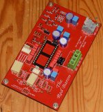
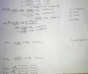
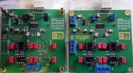
PCM1794 dual DAC questions
With both boards set to mono, one to right channel and the other to left channel, Do I just put opamps in the selected channel of each board?
If not, how do I connect the outputs?
If going with offboard solution for I/V etc, 22-27R seems to be an appropriate value for I/V resistors. Atleast if the same rules apply as for TDA1541A.
27R I/V
7.8mA (PCM1794 Iout).
V=IxR
V=0,078x27
V=2.106
22R I/V
V=0,078x22
V=1.716
Both the above examples are only valid if the Iout is the same in differential mode as in stereo mode.
Also, the datasheet suggest better performance with 4.5Vrms, that would give (closest standard value) I/V resistor of 56R for 4.368Vrms.
I'm waiting for a few 1206 300R 1% resistors to be able to complete the boards.
I have LME49710NA and LME49720NA as well as NE5532 and NE5534 and two LT1028(on the way).
The above is if I go with the onboard I/V etc.
I have plenty of transistors should I go discrete, and I have two pairs of Edcor XSM transformers, two 600:600 and two 10K:10K.
Attachments
- Status
- This old topic is closed. If you want to reopen this topic, contact a moderator using the "Report Post" button.
- Home
- Source & Line
- Digital Line Level
- Modular DAC project, questions and updates