Jitter test, etc.: http://www.collinsaudio.com/Prosound...unn_Jitter.pdf
J-test is for deterministic jitter (i.e. can be seen as spurs on an fft), not for close-in phase noise.
The original paper: http://s3t.it/data/uploads/docs/digi...-equipment.pdf
Ok. Thanks. Good reading.
I meant more from the stand point of correctly setting up REW with J-TEST in the signal generator and the RTA settings such as Hann window.
I just want to know more of the details for correctly setting with REW the first time instead of making a silly mistake.
Can you explain in detail how to perform such jitter measurements?
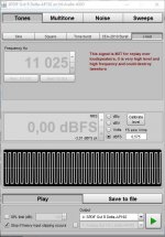
It is actually very easy. You have the JTest signal in REW. You may have to check from Windows sound settings whether you are using 16-bit or 24-bit.
I don't know if there is an "official" way to perform JTest (meaning window or averaging parameters).
Attachments
Last edited:
Ok. My biggest issue is that my SPDIF output stops working with ASIO drivers... [And under Windows 10 that is required for REW to use 24 bit samples and do J-Test.]
So no jitter measurements until (and if) I can get the Creative Professional/E-MU 1820 up and running on the ancient Vista machine.
An alternative would be trying to get the SB0490 and REW working under Linux (I have Linux Mint on another machine). But with all the problems getting the SB0490 to work properly under Windows 10 I am not sure I want to jump down that rabbit hole.
Yet another reason to get the E-MU running since currently my ES9038Q2M measures (2nd and 3rd harmonic) at the limit of my SB0490 ADC. (The 2nd harmonic measures exactly like the SB0490 loopback.)
Last edited:
There is a way that should get around windows sound engine messing up your test signal when non-ASIO drivers are used, but its sort of a pain to deal with. You have to set the preferences of the sound device to match the exact sample rate and bit-depth of your test signal. Also, turn up the windows volume level setting for the sound device to max. I used that method before and checked to make sure the audio was unmodified. In that particular case windows does not resample your digital test signal, at least it didn't used to.
There is a way that should get around windows sound engine messing up your test signal when non-ASIO drivers are used, but its sort of a pain to deal with. You have to set the preferences of the sound device to match the exact sample rate and bit-depth of your test signal. Also, turn up the windows volume level setting for the sound device to max. I used that method before and checked to make sure the audio was unmodified. In that particular case windows does not resample your digital test signal, at least it didn't used to.
Thank you. I already do those two things. However REW runs only 16-bits with Java drivers (on Windows 10, not Linux). I am under the impression that J-Test requires 24 bits? Is that not correct?
With ASIO drivers the problem is that nothing comes out of the SPDIF of the SB0490.
With the Zoom R24 24 bits works fine but that doesn't have an SPDIF. Sigh.
Last edited:
It is actually very easy. You have the JTest signal in REW. You may have to check from Windows sound settings whether you are using 16-bit or 24-bit.
I don't know if there is an "official" way to perform JTest (meaning window or averaging parameters).
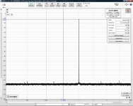
So I used (24-bit) Creative Professional/E-MU 1820 ASIO drivers with REW on Windows Vista and obtained the attached spectrum while measuring my ES9038Q2M board.
Does this look right? Should I conclude that the jitter is very good?
Attachments
Last edited:
When You do 'jitter testing', You should push for highest frequency resolution (and you did it ~right, do not have 'skirts' down around the carrier).
Do the largest FFT that you can afford; do the highest signal level that you are capable of (close to 0dB FS on the dac, which is still not clipping, not dirty)
That way one can go down to - 170dB noise floor.. But it's not a must. ~160 is the general value. You will see better the spurie getting out the floor.
And it is possible to open the zoom out fully, 0Hz-24 kHz in your case. Everything included is still anharmonic dustortion (the first harmonic would be at 24kHz..)
Ciao, George
I guess thin film 1206 resistors would also work fine. I'm just used to MELF resistors. And actually they are interchangeable with the PCB package I use in my layouts (even 0805 resistors can be used).
What brand/series of MELF resistors did you use? I ask since I am wondering what temperature coefficient was necessary to reach the distortion performance levels you achieved. I am tempted to guess that they are reasonably standard/general purpose metal film and do not need to be exotic.
So far I have used standard/general purpose 1% metal film (which I did hand match later) for my PCM1794 and ES9038Q2M. (They are both current output, however.)
What brand/series of MELF resistors did you use?
I buy most of the components from Mouser. MELF resistors are typically from one of these series (depending on price/availability):
Vishay Beyschlag MMA
Vishay Draloric SMM
TE Holsworthy SMA-A
Welwyn WRM
If you don't mind me asking what are your thoughts on the necessity of using anything other than good quality general purpose 1/4W 1% metal film in something like the PCM1794 or ES9038Q2M DAC? (I/V in particular, also the output filter.)
My assumption was that nothing more exotic or expensive was needed to keep any resistor contributions to distortion far below that of the DAC and op-amps. I ask since I am not not sure there is a solid technical argument to use much more expensive CMF/RN series or similar.
I am matching the resistors to better than 0.1% but that is a different issue. (Did you bother doing that?)
IMO any generic 1% metal film should be fine for DACs. If better matching is needed I usually opt for 0.1% resistors rather than trying to match 1% resistors.
That is what I was thinking.
What are your thoughts on needing anything better in a power amplifier? (Aside from obvious power dissipation requirements for emitter resistors.) Are there any locations besides the feedback where better resistors (temperature or voltage coefficients, etc) are needed?
I ask since after putting all the effort into making the PCM1794 DAC (and improving the ES9038Q2M I/V, filters and power supplies) I am fine tuning my project amplifiers which are obviously much higher THD than the DAC. Just trying to make the amplifiers as suitable a match for the DAC as possible.
Last edited:
@bohrok2610
Is this possible to you that you share your source code for STM32F030 witch that control AK4118?
Is this possible to you that you share your source code for STM32F030 witch that control AK4118?
Hi bohrok2610,
Thanks for sharing your work! I'm looking into implementing a SPDIF to I2S circuitry and the solution with 4118+4137 looks good!
Purpose is for a homelab project of building power amplifier with digital input.
I have difficulties to understand how work a a SRC chip, my understanding is that the SRC can accept every fs input stream (from 44.1k to 192k for example) and output a chosen fixed Fs (for example 96k). This sound right ?
There is no way to output the same FS as input ? For example 44.1k in => 44.1 out, 48k in => 48k out ? Maybe with bypassing the SRC but with the loose of jiter removal of SRC right ?
Also datasheet explain there is no need for external oscillator, you use one, why ?
If output Fs can change between 44.1 and 48k what about input oscillator frequency ? Should also switch between 22.579 and 24.576 ?
What kind of oscillator you use in you design ?
My goal is to interface two digital inputs to feed a dac (a ak4490 🙂 ), on SPDIF receiver with a 4118 AK IC and one Bluetooth from a BM83 Microchip module. Both streams are I2S, I think using SRC chip to remove jitter from BM83 module can be a good idea with a digital mux just like you did.
Have a fun day!
- Home
- Source & Line
- Digital Line Level
- Modular AK4490 DAC