Hi All,
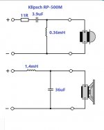
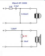
I have a pair of speakers with the crossover as in the attached drawing.
I feel/hear that there is kind of a "hole" in the midrange band (at about 1-4khz), looking at the drawing and placing it's values in few crossover simulators (online) it seems that the crossover point is at about 1.8khz (1.5khz according the speaker spec sheet) and there is a big "suckout" around the crossover point (-12db).
I don't want to re-design the original crossover, just maybe to improve it a little, I noticed that by changing the value of the 36uF capacitor (according to the simulator) in parallel to the woofer to 3uF improve this "suckout" from -12db to about -7db and the crossover point is now 2,290hz.
Does anyone have an idea why the manufacturer chose to put 36uF capacitor (considered as a large value) across the woofer? beside the crossover point does it has any other effect on the speaker performance like phase shift or something else?
According to the label on the back of the speaker the speaker has 8 ohm impedance, I measured 3.3 ohm resistance across it's binding posts.
Thanks
Attachments
Last edited:
Usually there's the "invert polarity" trick when you find a suckout at Fc
Probably the original tweeter is mounted with inverted polarity so that the two drivers don't emit in anti-phase at Fc.
The same "trick" is dictated by the filter formulas, as the signal gets phase rotated 90° by the R-L-C- components at each step of filter order. So for 2nd order you get 180° which means anti-phase and you just connect the tweeter with reverse polarity
I feel/hear that there is kind of a "hole" in the midrange band (at about 1-4khz), looking at the drawing and placing it's values in few crossover simulators (online) it seems that the crossover point is at about 1.8khz (1.5khz according the speaker spec sheet) and there is a big "suckout" around the crossover point (-12db).
If you don't know the FR of the drivers on the baffle without crossover and their impedance you can't simulate anything. The FR and impedance aren't flat so all online crossover simulators work with false assumptions, and their outcome is rubbish.
Feel assured that if Klipsch says that the crossover point is 1.5KHz, then it is at that frequency.
I don't want to re-design the original crossover, just maybe to improve it a little
Improving or redesigning a crossover (the effort is the same), means you need reliable and calibrated measurement gear. Without it you are essentially shooting in the dark.
So for 2nd order you get 180° which means anti-phase and you just connect the tweeter with reverse polarity
That is not fully correct. The drivers have to be connected with reversed polarity if the ***acoustic*** slope is LR2. The electrical order of the crossover will sum to the driver behavior, so the combined slope is almost always bigger than the electrical one. For the specific case it can easily be an acoustic LR4 crossover, thus the drivers are connected with the same polarity.
Having said all that, maybe the drivers are connected reversed in respect to what is the correct position. This would be strange but possible. If you don't like the sound of the speakers sell them, without knowing what to do (and we can't either without FR and impedance curves), you can't improve anything.
Ralf
Feel assured that if Klipsch says that the crossover point is 1.5KHz, then it is at that frequency.
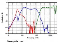
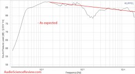
Here are 2 measurments of the bigger brother (RP-600M) from Audiosciencereview.com and Stereophile.com that shows that the crossover point is higher than the 1.5khz in the specsheet.
The same for the 96db very optimistic senitivity compared to the measured 89db senitivity.
So with a lot of respect to Klipsch the measurments shows a bit different story.
Attachments
I'd first try reversing the phase as this is the usual cause of a deep hole at the crossover.
Both of the drivers are in phase.
Please see #185 in here:
John Atkinson response at Audiosciencereview.com
It appear that reversing the tweeter polarity will cause the "suckout" go deeper.
That is not fully correct. The drivers have to be connected with reversed polarity if the ***acoustic*** slope is LR2. The electrical order of the crossover will sum to the driver behavior, so the combined slope is almost always bigger than the electrical one. For the specific case it can easily be an acoustic LR4 crossover, thus the drivers are connected with the same polarity.
Both of the drivers have the same polarity.
Shouldn't LR4 filter have more components than 1 capacitor and 1 inductor? as far as I know and please correct me if I'm wrong LR4 filter is "doubled" LR2, isn't it?
Thanks
Acoustic LR4 often can be accomplished by electric 2nd or 3rd order crossovers. That is because the drivers aren't resistors and don't have linear transfer functions.
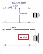
It is impossible to make a proper modification without measurement, but do try replacing the 36 uF capacitor with 10 uF.... there is a big "suckout" around the crossover point ...
Please report the findings.
Last edited:
Come to think of it, yes. I'll bet you a beer it's a misprint. I'd be looking for other circuit diagrams that confirm this.
It's purpose would be to create a 2nd order lowpass, in conjunction with the coil. The value is quite high, you'd expect something like this with a 4Ω driver only and that would still cause a ripple in the passband. Only theoretically speaking of course, we have to take the impedance and the acoustic transfer of the driver in the enclosure into account.
Come to think of it, yes. I'll bet you a beer it's a misprint. I'd be looking for other circuit diagrams that confirm this.
Well....it's not a misprint, it's the actual values taken from my speaker's crossover.
It's purpose would be to create a 2nd order lowpass, in conjunction with the coil. The value is quite high, you'd expect something like this with a 4Ω driver only .
You are correct, It is a 4 ohm woofer, Klipsch mentioned in the speaker spec sheet a 1500hz crossover point.
I'm considering replacing it with 3.3uF which theoretically create 2240hz crossover point.
Nope, it goes together with the L value, as it's a LC network. You may want to attenuate the action of C, so you might insert a R between 0.1 - 2.7 Ohm (10-25 W depending on the current/resistance) in series with a leg of that capacitor
Off the top of my head I would guess the shunting cap on the woofer to be around 22 µfd depending on the actual impedance, so not too far from the 36µfd.
- Home
- Loudspeakers
- Multi-Way
- Modifying speaker crossover