Hi, I am hoping to get some help to planning the modification of my Sim-Audio Moon 250i amplifier. I have uploaded a picture of the main circuit board. Please can anyone tell me what is what on the board. I would really appreciate your help, thanks in advance.
Attachments
Hi, I am hoping to get some help to planning the modification of my Sim-Audio Moon 250i amplifier.
I have uploaded a picture of the main circuit board. Please can anyone tell me what is what on the board.
Surface mount components are difficult to work on, if you have no experience with them. You'd also need a schematic, which doesn't seem to be available.
Last edited:
I won't be carrying out any of the work myself. I am using a company that specialises in modifications. The only problem is, they generally only modify source equipment and not amplifiers. So I was hoping to find out as much as I can, so I choose and provide the components that will be replaced. If anyone can explain the sections of the amp and what parts would benefit most from being replaced that would be great.
Member
Joined 2009
Paid Member
You've asked a rather big and open ended question - without realizing perhaps. To get more specific advice you could explain what you goal is - i.e. what problems you are trying to solve or what benefits you are looking for. And without a schematic it will be difficult to get more than generic answers.
I won't be carrying out any of the work myself. I am using a company that specialises in modifications. The only problem is, they generally only modify source equipment and not amplifiers. So I was hoping to find out as much as I can, so I choose and provide the components that will be replaced. If anyone can explain the sections of the amp and what parts would benefit most from being replaced that would be great.
Think I'd wait on this until you have reason to expect that the work will actually produce significant improvements in the sound.
Sorry if it's vague. I am basically trying to upgrade any weak links. I would like to replace any component that can be improved upon, to try and extract every drop of performance from the amplfier. I have already brought 11 new resistors to replace all the large resistors. I would like to replace the 7806 voltage regulator which I think is powering the pre-amp section. I have already brought three new power supply filter caps but I am unsure whether to replace all the Wima caps and the SMD caps. Does anyone have any thoughts on this for me?
I am fairly confident that these modifications will improve things as had my source equipment fully upgraded and it made a huge difference. I am not sure if it will make such a tangible improvement with an amplfier but I am definitely prepared to give it a go!
Wow , it a "blameless" with zener regulated IP pair and a simple EF2 - all for $2500.
Only 20V/uS slew -VFA. The bigger model (330i) is a 2 pair output stage with the same front end = $15K+! 😱
For more "grunt" , just some larger main supply caps. The rest of the amp is all
top quality wima poly /solid electro caps. They also might be using the "semelab"
audio BJT's (best BJT out there).
PS - If you believe in "burn-in" of poly and solid caps - like the reviewers of this amp , then you
also believe that replacing these already good components with esoteric "audiophool" parts
will really make a difference.
OS
Last edited:
Thanks for the advice, I have brought Mundorf AG Lytic supply caps to replace the two Nippon and single Nichicon supply caps. Unfortunately, due to the lack of space I can't increase the values. All the Wima caps are 0.1uf and I am tempted to swap some or all of these for Jupiter Audio Copper Foils which are meant to be second best only to Dueland Cast! Can anyone advise what are the most critical Wima caps that would benefit the most of being replaced? Also, does anyone know what the very best solid Polymer caps are?
Welcome to diyAudio IPOP 🙂
I would guess that the 7806 reg probably just powers any logic/control circuitry/LED's and so on. Its to low a voltage to be powering a preamp.
I don't want to dissuade you from having a go but tbh I think you are only going to devalue the amp by just randomly changing parts. Fitting oversize parts (I'm thinking caps and the like) can look messy.
I know that's probably not what you wanted to hear.
Ipop , I did not mean to be harsh with my comment.
But , by placing off-size components , components of different material .... you
might offset any fine tuning they (moon) did with parasitic capacitances, loop gain ,
stability.
So , any perceived improvement by upgrading might be countered by disturbing
the careful engineering (layout) of moon's design staff.
OS
Sorry if it's vague. I am basically trying to upgrade any weak links. I would like to replace any component that can be improved upon, to try and extract every drop of performance from the amplfier. I have already brought 11 new resistors to replace all the large resistors. I would like to replace the 7806 voltage regulator which I think is powering the pre-amp section. I have already brought three new power supply filter caps but I am unsure whether to replace all the Wima caps and the SMD caps. Does anyone have any thoughts on this for me?
Nobody builds an expensive, high-end amplifier like this with weak links. It presumes that any ham can come up with a better performing amplifier than the designer just by doing a cap-rolling routine. All you can really hope to do, regardless of whether you fit expensive boutique brands, is slightly alter the perceived sound. Maybe different caps seem impressive at first but likely only temporarily before any effect becomes tedious over time, requiring another round of "mods" every so often when the cash is available. IMV, this is acute boredom at work rather than a worthwhile pursuit.
More to the point, if your modifying service has no clue about or simply doesn't work on amplifiers, you surely have to think about how risky getting them to work on your amplifier would be, under only your direction. Also consider that obvious fiddling about inside an expensive amp drops the resale value greatly. Few will buy it at nominal value on the strength of changes they probably want to make and hear for themselves.
Thanks for all your responses. I appreciate your honesty and frankness, so please feel free to say whatever you like as I won't get offended. The company that is upgrading it has upgraded amplifiers before but they don't specialise in it so I wanted to get some expert recommendations so I can maximise the effectiveness of the modification. I am basing the changing of parts on reviews and research. For example, the Wima caps are rated by Humble HiFi capacitor test as being a 7 where as Dueland Cast caps are rated at 14. So my thinking was that if I replace some or all of these caps with caps that perform much better and suit my musical tastes, then it would improve the amplfier. Maybe I am being very naive! I do admit to being a novice, although I imagine that is already fairly obvious! So with that said, any further advice is very welcome.
I swiped "Humble HiFi....." into Bing and got this,
Humble Homemade Hifi
So... for what it is worth 😱 this is what I think. When I started out in electronics (and it was the day job for many years after) I "believed" that replacing selected parts in a particular amp or whatever would make big differences. And they did, I was sure of it but over time I began to realise that much of that was "expectation" and wanting it to be better having put the effort and work in.
Nowadays I look at the problem more logically and realise and understand that it doesn't always work like that. For example, if you replace one cap for a different type that happens to be much larger physically, or of different construction then it may be prone to pickup of stray interfering fields due to its larger size. It may be wound differently... some small cap types such as polystyrenes can be considered "directional" in that you can take advantage of the outer layers of the construction and use that as a shield by connecting the "outer" terminal to the lowest impedance point of the two connections available.
I ran a passives test some while back. Photo in post #23. Should be easy to tell component differences... but was it 😀 (the files are long since deleted I'm afraid)
http://www.diyaudio.com/forums/everything-else/250147-listening-test-part-1-passives.html
I know where you are coming from as many people share that view. I still like to think that the very best quality components, like Dueland, Jupiter etc. can make a considerable improvement, but maybe I am just being wishful! That aside, can anyone help me understand what each section of the main PCB are responsible for? I don't have the schematics and it's very unlikely that I will be given access to them. So if anyone can figure it out just by the picture I posted, I would be very happy and interested to hear from you. Many thanks in advance. 😀
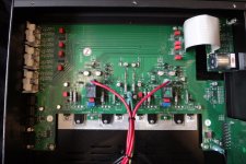
From the photo...
Top left near the sockets are two surface mount (SMD) IC's. What is the device number of these ? They could be some form of electronic input switching.
Top right are two 8 legged IC's Opamps ? What are the markings ?
The black boxes on the PCB look like relays (speaker feed).
Output transistors are all bolted to the heatsink. The pairs with a green clamp look like they will be for temperature compensation. The big ones are the output transistors and the medium sized the drivers.
Bottom left is another SMD IC. What is that type marked as ?
1. I still like to think that the very best quality components, like Dueland, Jupiter etc. can make a considerable improvement, but maybe I am just being wishful!
2.That aside, can anyone help me understand what each section of the main PCB are responsible for? I don't have the schematics and it's very unlikely that I will be given access to them. So if anyone can figure it out just by the picture I posted, I would be very happy and interested to hear from you. Many thanks in advance. 😀
1. "wishful" = subjective. Sort of like "faith". 😀
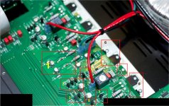
2. To make up for my snippy remark , I reverse engineered the 250i. It is a LIN
with an EF2.
(below 1)
1 = zener voltage reference , 2 = current mirror (wilson ?) , 3 = input pair
4/5-5 = the VAS (voltage stage), 6 is the actual EF2 output stage while 7
is a complimentary bias spreader.
Being done "small" in SMD form allows for this topology to have close tolerances
and be free from parasitic capacitances. Hence , my comment that adding large
expensive parts will DETRACT from the enginneered layout.
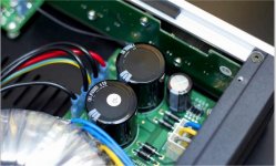
The power supply (below 2) is 35mm /10Kuf@63V capacitors - 12K-15KuF might
fit if they are < 65mm tall. The black diodes below the main caps could be "snubbered" with .01uf caps or upgraded to to-220 devices.
I KNOW any of the other changes would most likely devalue the amp and degrade
performance. BTW - VERY nice amp !!
OS
These would give this amp more "grunt" with difficult passages.
Attachments
I am back!
Unfortunately I got majorly sidetracked and had to forget about upgrading the amplifier for a while (2 years)!!! But it's time the plans got dusted off and looked at again. Thank you for all your previous relies and help. I will admit that I have no real knowledge of how this amplifier works and so I am hoping that people like yourselves with much more knowledge than me can help me to make this amplifier as good as it possibly can be. If anyone can suggest parts that can swapped to improve performance I would be very grateful. Thank you.
Unfortunately I got majorly sidetracked and had to forget about upgrading the amplifier for a while (2 years)!!! But it's time the plans got dusted off and looked at again. Thank you for all your previous relies and help. I will admit that I have no real knowledge of how this amplifier works and so I am hoping that people like yourselves with much more knowledge than me can help me to make this amplifier as good as it possibly can be. If anyone can suggest parts that can swapped to improve performance I would be very grateful. Thank you.
If you can help me I would really like to know:
What the 2 chips and 4 Wima caps on the left do?
What the 2 chips and 4 Wima caps on the right do?
What the smaller 2200uf filter cap does?
What the 4 small diodes do next to it?
Finally, what parts could or should be replaced with better performance parts and what these parts are?
Thank you very much in advance. 👍😁👍
Ok, I think I know what the 4 diodes do! They form a bridge rectifier to block AC and just allow DC (I said I was a novice). I am guessing that the smaller 2200uf filter cap and smaller diodes are for the pre-amp and the larger 10000uf filter caps and diodes are for the power amp. Please tell me if I am right or wrong. If I wanted to replace the diodes for better ones as Ostripper mentioned. Should I use Schottky diodes or ultra fast diodes? Please can someone recommend the very best ones, preferbly a specific type. Research tells me that the International Rectifier Schottly 8TQ100 is the best but I am not sure. Thanks.
- Status
- Not open for further replies.
- Home
- Amplifiers
- Solid State
- Modifying Moon 250i Amplifier