I have Heathkit AA 151.
1. What is AF amp circuit? (6AU6 and 6AN8A)
What is XTAL (Crystal) Phono in input section?
2. I've found that it has EQ and ST<->Mono Circuit.
Do you think it is worth of keeping them? Well, I like
pure signal path better.
3. If not worth, how can I eliminate them?
How about just bypassing 6AU6 and 6AN8A (so-called AF Amp circuit) and adding some Rl between them?
Thanks.
I ran a Google search to find a schematic. It turns out that the AA-151 is the same as the SA2, except for 6EU7s instead of 12AX7s.
If you examine the linked schematic, you will see that the 6AN8 forms the voltage gain and phase splitter stages of the power amp section. You can't bypass the 6AN8.
What are your objectives? What sources do you use?
If you examine the linked schematic, you will see that the 6AN8 forms the voltage gain and phase splitter stages of the power amp section. You can't bypass the 6AN8.
What are your objectives? What sources do you use?
My resource is
original schematic. (Sorry, I forgot to attach it.)
http://mcnally.cc/pics/aa151l.jpg
http://mcnally.cc/pics/aa151r.jpg
http://mcnally.cc/amps.htm
Well, 6AN8 works for both "AF AMP"
My question is
1. what is "AF AMP"? "AF AMP" looks like a circuit of EQ and Mono-Stereo SW to me. 6AU6 and 6AN8 (pentode part) seem to
work for "AF AMP". If it is not important, I want to eliminate
it.
2. However, Signal goes through 6EU7 -> 6AU6 ->6AN8......
Is it too much gain?
The 6AN8 is critical to the operation of the EL84 "finals". You can't get rid of it unless you do a complete redesign.
If a CDP is your only source, you can bypass everything in front of the 6AN8s. Wire the I/P RCA jacks to 10 KOhm volume controls. Connect the wipers of the pots. via 68 nF./63 WVDC caps to the 6AN8 pentode control grids. Connect the control grids to ground via 100 KOhm/1% metal film resistors.
If a CDP is your only source, you can bypass everything in front of the 6AN8s. Wire the I/P RCA jacks to 10 KOhm volume controls. Connect the wipers of the pots. via 68 nF./63 WVDC caps to the 6AN8 pentode control grids. Connect the control grids to ground via 100 KOhm/1% metal film resistors.
Xtal phono is for high-output cartridges, rarely seen these days, made from piezoelectric crystals. They were most common in VERY cheap phono systems back in the '50s and '60s.
Hi zxx123
Disconnect the cathodes of V4/5 from the cathodes o V9/10. And use a cathode resistor of 200 Ohms bypassed with a electrolytic capacitor , for each pair of output tubes V 4/5 and V9/10.
That way you minimise the low frequency cross talk that ruins the stereo image.
Disconnect the cathodes of V4/5 from the cathodes o V9/10. And use a cathode resistor of 200 Ohms bypassed with a electrolytic capacitor , for each pair of output tubes V 4/5 and V9/10.
That way you minimise the low frequency cross talk that ruins the stereo image.
However, Signal goes through 6EU7 -> 6AU6 ->6AN8...... Is it too much gain?
For a CDP it is WAY too much gain. Look at the schematic. Notice that the 6AN8 pentode section is biased at 1.5 V. The 2 V. RMS O/P of a CDP is 2.8 V. peak. Without attenuation from a volume control, the O/P of a CDP will surely drive the amp into clipping.
Please provide a list of all the sources you intend to use with the AA-151. Incomplete info. makes providing reasonable recommendations VERY difficult.
If you plan on using a turntable, the phono section needs (IMO) to be reworked. Super low hum or not (6EU7), AC on phono section heaters is FUGLY.
Eli Duttman said:The 6AN8 is critical to the operation of the EL84 "finals". You can't get rid of it unless you do a complete redesign.
If a CDP is your only source, you can bypass everything in front of the 6AN8s. Wire the I/P RCA jacks to 10 KOhm volume controls. Connect the wipers of the pots. via 68 nF./63 WVDC caps to the 6AN8 pentode control grids. Connect the control grids to ground via 100 KOhm/1% metal film resistors.
Yes, CDP is only source. And I think I need to add a new volume pot.
However, is only 6AN8 enough to drive EL84? Moreover, NFB circuit of 6AN8's cathode may reduce the gain.
How about going from 6EU7 to 6AN8 (triode part for PI).
However, is 6AN8 enough to drive EL84? Moreover, NFB circuit may reduce the gain.
The 6AN8 is PLENTY all by itself to drive the EL84s. 1.1 VRMS of drive pushes the 6AN8 into clipping. The NFB is FINE, as it was part of the original designer's thinking process.
How about going from 6EU7 to 6AN8 (triode part for PI).
It MIGHT work. IMO, you should stay with the proven 6AN8/EL84 setup.
I think I need to add a new volume pot.
The schematic indicates separate L/R volume controls instead of ganged stereo volume and balance controls. IMO, that's a GOOD thing. All you need to do is remove the OEM pots. and insert 10 KOhm log parts in their place. Mouser stock number 31VJ401 is what you need.
The 68 nF. cap. connecting the pot. to the 6AN8 forms a filter in combination with the 100 KOhm grid leak resistor that keeps low freq. crud out of the amp. That, in turn, allows the value of the coupling caps. between the splitter and "finals" to be increased to 100 nF. The result is tighter, less tubby, bass as the low freq. error correction signal present in the O/P trafo is reduced. There's less phase shift inside the NFB loop too. 716P series Orange Drops are perfect for the replacement coupling caps.
Another sure fire tweak is to use separate bias networks for each pair of finals. Getting TIGHTLY matched pairs of tubes is tough enough. TIGHTLY matched quads are much more difficult to obtain than TIGHTLY matched pairs. Use 200 Ohm/5 W. resistors and 150 muF. 'lytics in the new bias networks.
BTW, how does the AA-151 handle the power on/off function?
Thanks. I will keep them.
It is just a normal power sw. See M5.
Eli Duttman said:
BTW, how does the AA-151 handle the power on/off function?
It is just a normal power sw. See M5.
doing same mod
I have an AA-151 as well that was cosmetically bad so i'm building a small amp from the salvaged parts. Having read the recommendations above i come up with this schematic, (changes/additions to original scheme are in boxes), please have a look and see if i interpreted correctly, or if i should change anything else?
Thanks,
Bill
Attachments
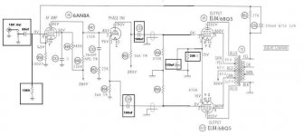
There's one other problem with design (which is a budget design). The magnetic phono input is out of phase (compared to the other inputs) as the phono amp is only one section of the 6EU7 (which inverts the signal). The high level inputs to (speaker) output are in-phase.
Regarding the 6EU7, it was a special tube for 3 reasons:
1- different basing arrangement to provide improved isolation of triode sections.
2- a special electrode assembly to reduce microphonics.
3- a helical-wound heater to reduce AC hum coupling thru CMRR.
In later years, the 6EU7 lost most of it advantages as manufacturers simply used a common 12AX7 assembly with the different basing arrangement. At this point, there was no advantage to using them. I have samples of both... and even an odd 12AX7 with helical heaters... seems they had leftover heaters from a 6EU7 run or the order was changed during the run.
Regards, KM
- Status
- Not open for further replies.
- Home
- Amplifiers
- Tubes / Valves
- Modifying Heathkit AA 151