Hi,
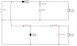
I've built the crossover below, but the tweeter is far to loud for my ears. How can I modify this design to attenuate the tweeter? Can I simply increase the 2R2 resistor in series with the tweeter, or will this mess up the impedance that the amp sees? Based on some experiments replacing that resistor, I think I'd have to increase it as much as 6 ohms to reduce the volume enough.
Tweeter nominal impedance is 8Ohms.
Thank you!
Attachments
If you increase the 2.2 ohm resistor, your XO frequency will shift, because it will "see" higher impedance. You can try an L-pad, increasing 2R2, and connect a resistor across the tweeter, something like 4R7 in place of the 2R2, and a parallel resistor of approx 12 ohm. OR, just inserting a resistor before the tweeter XO that might solve your problem.
Can I simply increase the 2R2 resistor in series with the tweeter, or will this mess up the impedance that the amp sees? Based on some experiments replacing that resistor, I think I'd have to increase it as much as 6 ohms to reduce the volume enough.Tweeter nominal impedance is 8 Ohms.
u!
If you increase the 2.2 Ohm resistor, you should add a resistor in parallel with the tweeter to bring the total impedance
back down to its original value of 10.2 Ohms so the crossover frequency stays the same. Both resistors affect the attenuation.
Last edited:
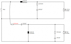
This is a harder problem than I expected. Thing is, you can't just take the tweeter level down without creating a hole in the midrange. So you need to adjust the capacitor as well. 4.7uF or 2.2uF depending on topology.
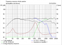
I came up with two ways of getting to roughly the same place. Resistor values are estimates based on the graph you provided. I tried to get rid of that 10kHz peak in the tweeter response too. I'd guess it's polycarbonate aka mylar, which usually does just that.
The circuit with the higher impedance is the series/zobel one. You can ignore my bass section, which differs with a different driver.
Attachments

Use an L-Pad of the same impedance as the tweeter, in this case, 8 ohms.
A fixed divider network, as PeteMcK suggested, isn't the easiest way since that isn't continuously adjustable like a regular L-pad. (His idea is a good one, though, if you had a definite idea of how much attenuation you needed and it is always fixed. Much less expensive than a good L-pad.)
The L-pad is dual potentiometers such that it maintains a constant impedance while allowing you to bypass as much or as little power to the tweeter as you want.
Vastly simpler than monkeying around with the crossover.
If you insist on altering the crossover, you'll need, as PeteMcK suggested, a series resistor and a parallel one so that you maintain the same overall tweeter impedance.
Try using the resistor as the first element in your HPF. Putting it just before the tweeter affects the transfer function, as the reactive elements before it see a different output load resistance. Using the resistor on the input side means the output load is unaffected and the x-over point changes only due to the up/down shift in tweeter level, not the corner frequency resistance.
Try using the resistor as the first element in your HPF. Putting it just before the tweeter affects the transfer function, as the reactive elements before it see a different output load resistance. Using the resistor on the input side means the output load is unaffected and the x-over point changes only due to the up/down shift in tweeter level, not the corner frequency resistance.
This is not correct.
It is indeed correct. We'll do a simple example of a 2nd order HPF. This circuit can go two ways: resistor before the cap, resistor before the tweet
In the former case, the resistor has nothing to do with the transfer function behavior of the circuit. It exists solely to control the voltage available to the subsequent elements.
Fc = 2000Hz
8 ohm load = 7uF cap, 900u inductor means down 3dB at 2000Hz.
Now, let's put in a 8ohm resistor before the load. We've lowered the nominal voltage 6dB, BUT, have an underdamped circuit. We are now 3dB UP at 2kHz because we have a high Q knee.
Put the 8 ohm resistor before the cap. We're down 1.414dB at 2kHz, and 3dB at 1500Hz, 1/4 octave which corresponds to having the exact same filter as before, only shifted -6dB in output voltage magnitude as I said.
Please simulate this circuit and you can prove it to yourself.
As it is hard to tinker with the passive crossover if your amp has high enough input impedance you could place a global passive notch filter in front of the amp. Then you wouldn't have to worry about actual driver and crossover impedances.
Now, take the one with the 8Ω before the filter, remove the fake woofer, turn on the active xover section and put in a +6dB boost, and save the sum response at the top (now the tweeter response) to the overlay. Remove the resistor, turn off the active boost, and add that to your three graphs.8 ohm before and after HP of 7uF and 0,9mH ( 0 ohm dcr).
Tweeter is assumed to have ideally flat FR and impedance.
Smart idea, but it won't solve his problem. With 10 kHz peak visible on the above FR response diagram...OR, just inserting a resistor before the tweeter XO that might solve your problem.
in mind, you want to address this precisely with a notch filter instead of lowering the entire treble. 😱
It is very hard to preserve the same high-pass transfer function while varying the value of only one resistor, to obtain the variable attenuation only. Almost the same is with the L-pad. Part of the problem is that tweeter has complex impedance, not a uniform resistance.
Simple and rather good approximate solution is a resistor before the high-pass filter, as recommended by lemans123. The notch RLC filter is better, but more complex.
Detailed computer simulation will find the best solution, of course.
Simple and rather good approximate solution is a resistor before the high-pass filter, as recommended by lemans123. The notch RLC filter is better, but more complex.
Detailed computer simulation will find the best solution, of course.
absolutely correct. Or maybe replace the tweeter entirely?Smart idea, but it won't solve his problem. With 10 kHz peak visible on the above FR response diagram
in mind, you want to address this precisely with a notch filter instead of lowering the entire treble. 😱
You could of course notch the polycarbonate 10kHz tweeter peak. What, 0.1mH, 2.7uF and 6R shunt? It happens my advice is based on experience of this type of tweeter. A Visaton DT94 with a phase plate to improve high end dispersion.
A Zobel of 7.5R and 1.5uF will do a similar job. Most of the output above the 10kHz peak will be rubbish anyway, so you won't miss it.
I'll leave you theoreticians to continue making this more difficult than it is. I have just been suggesting a cheapish fix. 😀
A Zobel of 7.5R and 1.5uF will do a similar job. Most of the output above the 10kHz peak will be rubbish anyway, so you won't miss it.
An externally hosted image should be here but it was not working when we last tested it.
I'll leave you theoreticians to continue making this more difficult than it is. I have just been suggesting a cheapish fix. 😀
You could of course notch the polycarbonate 10kHz tweeter peak. What, 0.1mH, 2.7uF and 6R shunt? It happens my advice is based on experience of this type of tweeter. A Visaton DT94 with a phase plate to improve high end dispersion.
A Zobel of 7.5R and 1.5uF will do a similar job. Most of the output above the 10kHz peak will be rubbish anyway, so you won't miss it.
+1 🙂
- Status
- Not open for further replies.
- Home
- Loudspeakers
- Multi-Way
- Modifying crossover to reduce tweeter volume