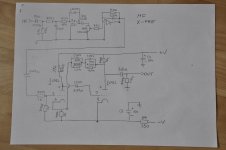
I've traced the schematic of the MM section only of the X-LP.
the 22pf is connected wrong, for the circuit to work, there should be a path for the resistors in the feedback network to connect to the inverting pin of the ic..
yes, but we have to correct mistakes when we find it.....
caught this one thru google search...😀
caught this one thru google search...😀
Hi,
this thread has been again dead for quite some time.
I still feel that this post belongs here as the MF X PRE modified by myself is coming directly from kepa1 who was a contributor in this thread.
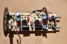
So thanks to kepa1 I came into possession of a nice looking not working x pre. I wanted to play with it as it looked like a nice project (tubes, relatively low voltages, nostalgia related to a once pricey sexy looking piece of equipment). kepa1 was kind to provide me with extra tubes, which proved to be useful as one inside the case has not survived the shipping from France, another one proved to be almost dead (kepa1 - if you reading this - I am not complaining!!!)
I was aware that there is an op amp in the circuit so the long term goal was to get rid of this. But first I had to bring the pre amp to life. This took one or two evenings and I was able to connect it to the system. The sound was very reasonably clean but with some harshness in the treble and also somewhat thin. It is difficult to describe not thin in the sense of poor transistor amplifier more like he response was tilted toward high frequences.
this thread has been again dead for quite some time.
I still feel that this post belongs here as the MF X PRE modified by myself is coming directly from kepa1 who was a contributor in this thread.
So thanks to kepa1 I came into possession of a nice looking not working x pre. I wanted to play with it as it looked like a nice project (tubes, relatively low voltages, nostalgia related to a once pricey sexy looking piece of equipment). kepa1 was kind to provide me with extra tubes, which proved to be useful as one inside the case has not survived the shipping from France, another one proved to be almost dead (kepa1 - if you reading this - I am not complaining!!!)
I was aware that there is an op amp in the circuit so the long term goal was to get rid of this. But first I had to bring the pre amp to life. This took one or two evenings and I was able to connect it to the system. The sound was very reasonably clean but with some harshness in the treble and also somewhat thin. It is difficult to describe not thin in the sense of poor transistor amplifier more like he response was tilted toward high frequences.
My redesign brief was short:
1. get rid of the op amp
2. keep everything in the existing case
3. do not mess up too much
So the time has come to get rid of the op amp.
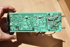
As there seems to be no circuit diagram on the net I had to reverse engineer it from the pcb.
Now, mind that I am not an electrical engineer. I am just a humble mathematician with a daily job which allows me to fund these kind of projects. If you see anything strange in the schematics please feel free to point it out. Also in the sequel if you see anything which can be done better let me know.
I was a bit surprised to see a quad op amp in the circuit. I could thing of one op amp per channel, but two? What I say was pretty bad: it seems that the vol pot has been sandwiched between two op amps.
1. get rid of the op amp
2. keep everything in the existing case
3. do not mess up too much
So the time has come to get rid of the op amp.
As there seems to be no circuit diagram on the net I had to reverse engineer it from the pcb.
Now, mind that I am not an electrical engineer. I am just a humble mathematician with a daily job which allows me to fund these kind of projects. If you see anything strange in the schematics please feel free to point it out. Also in the sequel if you see anything which can be done better let me know.
I was a bit surprised to see a quad op amp in the circuit. I could thing of one op amp per channel, but two? What I say was pretty bad: it seems that the vol pot has been sandwiched between two op amps.
Attachments
Removing the op amp was easy as there was a socket on the pcb. I just took it out. Then I bridged IN to 8 of the op amp (I was not brave enough to go to the other side of C208 - any thoughts on this? anyway the cap is Elna SilmicII which has Nelson Pass' blessing and is used in his ACA). Another bypass want from the slider of the pot to output 7 of the op amp. Mind that since the amp uses a dual power supply it is not possible to bypass the coupling can which comes next.
At this stage the sound has lost some of the harsh sibilance. And I still had a volume control and the source switch.
But still too thin to my liking.
My guess was that it was due to too small coupling caps. I beefed up the 0.22uF in front of input of the first half of the tube up to 1uF. This brought an improvement. Then I added another 2.2uF at the output (which proved to be very tricky given my design brief). Another improvement.
There is lots of presence but still too bright to my liking. Not sure where to go from here.
Also I do not understand the whole feedback from pin 6 of the tube to pin 3.
When I disconnect it it does not work. Any thoughts again?
More to come... ( at least in terms of sound impressions)
Attachments
Hello Gregje, I can't help much (save that the schematics are in the beginning of this thread) but I'm glad to see that this unit is in good hands!
Hi,
@kepa1: I certainly have much fun with it. Many thanks!
I am just wondering how much of the issues are coming from the lowish power supply.
But again, supplying something like 250V would certainly not work with the original enclosure! And the whole PCB would need to be redesigned.
@kepa1: I certainly have much fun with it. Many thanks!
I am just wondering how much of the issues are coming from the lowish power supply.
But again, supplying something like 250V would certainly not work with the original enclosure! And the whole PCB would need to be redesigned.
After studying the circuit of x-10d a bit more I realised that I have pretty much converted the x-pre into x-10d (there is a typo in the schematics I have posted above: I missed 1.8M biasing resistor in front if the grid of the second half of the tube).
In the threads about x-10d people confirm what I suspected: the feedback network from the anode of the second half of the tube (pin 6) to the cathode of the first half (pin 3) is used to shape the response correcting for all anomalies caused by the low B+.
Strangely nobody comments on the size of the coupling capacitors. I guess I am imagining things just like a DIY-er who changed something and is convinced it is superior to the previous state.
Gregje,
I came to the conclusion that the existing low B+ is a blocking problem.
In the end I'll pull one of the tubes and use its heater power budget to drive B+ higher and use CCS to get the 6DJ8 back to a sane operating point.
It's about all that can be done in the available space.
I've not done anything for a while due to "other commitments" (which are winding up now) but my thoughts are over in this thread
Hotrodding the MF-Xpre
- Status
- Not open for further replies.
- Home
- Design & Build
- Parts
- Modifying a Musical Fidelity X-Pre