Re: Post 13
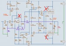
R7 is quite often seen in good amplifiers.
But likewise often not in many amateur amps.
Usually a quite low value resistor.
What I have understood, it gives better control of the output stage Bias Current.
U4, BD139 senses the heat.
And as transistors get Volt Base-Emitter ~2 mV lower / 1 degree C increased temperature,
BD139 will reduce the voltage between Output Base-Base,
when heatsink get's hotter.
If heatsink get's 40 C hotter, the Voltage b-e of U4 will be ~ 80 mV less.
This difference is multiplied by (R8+R13+R18)/R18.
Which is like x4.
Result is:
Temp +40 C = - 4x 80 mV = -320 mV,
between Output Base-Base.
Also those both Output big transistors will have less Vb-e.
And if this is the same value as -320mV,
then the average voltage across R9+R15 will stay almost the same.
We have an ideal temp compensation, to avoid thermal runaway
and get the amplifier overheated.
------------------------
For some reason this Vbe multiplier temperature compensation is not 100%.
Not without such little resistor.
About C4 which is across the R7, 47 Ohm.
I have not noticed this cap in amplifiers before, but ..... as I can understand:
As the temp compensation is DC Level Thing,
the C4 makes R7 'more invisible' for AC signals,
so that R7 does not effect the higher frequency Audio signals, hardly anything.
GEirin said:Hi.
What is the function of the R7//C4.
Thank.
Geirin.
R7 is quite often seen in good amplifiers.
But likewise often not in many amateur amps.
Usually a quite low value resistor.
What I have understood, it gives better control of the output stage Bias Current.
U4, BD139 senses the heat.
And as transistors get Volt Base-Emitter ~2 mV lower / 1 degree C increased temperature,
BD139 will reduce the voltage between Output Base-Base,
when heatsink get's hotter.
If heatsink get's 40 C hotter, the Voltage b-e of U4 will be ~ 80 mV less.
This difference is multiplied by (R8+R13+R18)/R18.
Which is like x4.
Result is:
Temp +40 C = - 4x 80 mV = -320 mV,
between Output Base-Base.
Also those both Output big transistors will have less Vb-e.
And if this is the same value as -320mV,
then the average voltage across R9+R15 will stay almost the same.
We have an ideal temp compensation, to avoid thermal runaway
and get the amplifier overheated.
------------------------
For some reason this Vbe multiplier temperature compensation is not 100%.
Not without such little resistor.
About C4 which is across the R7, 47 Ohm.
I have not noticed this cap in amplifiers before, but ..... as I can understand:
As the temp compensation is DC Level Thing,
the C4 makes R7 'more invisible' for AC signals,
so that R7 does not effect the higher frequency Audio signals, hardly anything.
GEirin said:Hi Lineup.
Thank you very much for your detailed explanations.
GEirin
why this little simple saying makes me so happy: tank u
... really do not know
 .. or maybe i do
anyway.
have never costed me one € Euro or one Swedish crown SKr
to express my gratitude
...and give away my Thank U Veru Muchos Gratias
GEirin 🙂 my friend
Send my respect & honor to your parents.
If they are alive.
They sure did a good job.
With you, their young child.
------------------------------------------------
There are some things, among we people,
that are far far more important, than post some diy audio ideas & knowledge.
😎 This is to spread the respect and goodwill to wards other humans 😎
... instead of contribute into this world
your war,
troubles,
your suspect suspicions,
your misunderstandings & intolerances and your deaths & sorrow
Lineup - sweden june 2008
Hey guys !
sorry i´m late! cause , i need much time for my diploma thesis ...
- but the measurements on the circuit will come soon as possible...
by the way, the amp is working already with updated parts, and it sound´s very nice !!!
bye & best regards
ECBLN
sorry i´m late! cause , i need much time for my diploma thesis ...
- but the measurements on the circuit will come soon as possible...
by the way, the amp is working already with updated parts, and it sound´s very nice !!!
bye & best regards
ECBLN
Hi everybody!
I happen to also have one old Grundig SV2000 and I'm trying to restore it.
Only today I was able to test it for the first time but the right speaker doesn't work. I think the problem is not the speakers, I've switched them and and the problem seems to be the amplifier.
Does anyone have the full schematics?
Also does anyone have a clue of where should I start looking for the problem? (my first guess is that one of the amplifier circuits is not working)
Best regards
The Darlington output is already changed to BDV64/65 type.
(they are similar to the special GP-type´s from Grundig)
Although working well generally , BDV64/65 pair
is out of date performance wise for audio purposes.
Sanken s MP1620/MN2488 would be far better.
2SB1647/2SD2560 , 2SB1670/2SD2401 and
2SB1648/2SD2561 fit the job as well...
- Status
- Not open for further replies.
- Home
- Amplifiers
- Solid State
- modify my old 80s amp