That's an interesting suggestion, would that bypass the bass and treble pots as well?
Yes, but.... I think before all else you should do the tone control capacitors because it is easy and won't cost that much.
To do the "bypass" you would lift the end of R8 that connects to R10 so the free end of R8 can be switched back to R10 or to the center point of an alternative divider network.
The resistor (A) at the top end of the divider is taken to the C6 on the side that connects to R14. The resistor (B) lower end of the divider is taken to the ground line i.e. that between the circled points 2 and 6.
This is a negative feedback circuit and the gain due to the divider network is determined from the value of (A) added to (B) and the result divided by (B).
Before considering values, (A) added to (B) is in parallel with the impedance of the tone control section output and consideration will need to be given to increasing the value of C6. If you halve the impedance seen by that part as you would need to double it in value otherwise the low frequency response will be affected.
The power amplifier has a voltage gain of 14 times - relatively low - you will need much more than that to boost spec level signals of 150 millivolts to get some usable power. Of course CD players can output 2 volts so you will need to consider your uses.
A possible starting point for resistor (B) at 1.5k which matches R11 - this chosen should your interest be in a pure line stage after considering what follows.
Power is related to output R.M.S. voltage and load - power equals voltage squared by load.
The required R.M.S voltage output to deliver 45 watts into 8 ohms is 18.97. Dividing by 14 gives 1.35 - the voltage needed at the power amplifier input. Divide 1.35 by 0.15 to find the gain factor needed to boost the low level inputs and you get 9 times.
In harness with a resistor (B) of 1.5k that would call for resistor (A) to be 12k. You might try using a variable resistor in place of resistor (A) to experiment. Use your scope to ensure the output level is the same as with the tone controls selected.
I would be concerned about the added loading of a 13.5k series combination on the tone control output and C6. I would try to alleviate by doubling (A) and (B) resistor values to 24k and 3k respectively.
However I am not comfortable doing anything that might cause a lop sided balance to make things rough for the negative feedback loop when switching between modes. To do a proper job the modified network would need to be redesigned an undertaking you would have to do yourself. I have already quoted an amplifier that you can investigate for a starting point.
If you want a plain line stage disconnecting one end of R14 will take the tone controls out of circuit and you can experiment with the (A) and (B) resistor network and hardwire these in using the highest practical values.
An externally hosted image should be here but it was not working when we last tested it.
Yes, but.... I think before all else you should do the tone control capacitors because it is easy and won't cost that much.
To do the "bypass" you would lift the end of R8 that connects to R10 so the free end of R8 can be switched back to R10 or to the center point of an alternative divider network.
The resistor (A) at the top end of the divider is taken to the C6 on the side that connects to R14. The resistor (B) lower end of the divider is taken to the ground line i.e. that between the circled points 2 and 6.
This is a negative feedback circuit and the gain due to the divider network is determined from the value of (A) added to (B) and the result divided by (B).
Before considering values, (A) added to (B) is in parallel with the impedance of the tone control section output and consideration will need to be given to increasing the value of C6. If you halve the impedance seen by that part as you would need to double it in value otherwise the low frequency response will be affected.
The power amplifier has a voltage gain of 14 times - relatively low - you will need much more than that to boost spec level signals of 150 millivolts to get some usable power. Of course CD players can output 2 volts so you will need to consider your uses.
A possible starting point for resistor (B) at 1.5k which matches R11 - this chosen should your interest be in a pure line stage after considering what follows.
Power is related to output R.M.S. voltage and load - power equals voltage squared by load.
The required R.M.S voltage output to deliver 45 watts into 8 ohms is 18.97. Dividing by 14 gives 1.35 - the voltage needed at the power amplifier input. Divide 1.35 by 0.15 to find the gain factor needed to boost the low level inputs and you get 9 times.
In harness with a resistor (B) of 1.5k that would call for resistor (A) to be 12k. You might try using a variable resistor in place of resistor (A) to experiment. Use your scope to ensure the output level is the same as with the tone controls selected.
I would be concerned about the added loading of a 13.5k series combination on the tone control output and C6. I would try to alleviate by doubling (A) and (B) resistor values to 24k and 3k respectively.
However I am not comfortable doing anything that might cause a lop sided balance to make things rough for the negative feedback loop when switching between modes. To do a proper job the modified network would need to be redesigned an undertaking you would have to do yourself. I have already quoted an amplifier that you can investigate for a starting point.
If you want a plain line stage disconnecting one end of R14 will take the tone controls out of circuit and you can experiment with the (A) and (B) resistor network and hardwire these in using the highest practical values.
Last edited:
Hi jooch,
Setting bias current the way Carlos has mentioned would be a great exercise, you would learn a lot. Since I have almost always had a distortion analyzer, I could investigate many things. Consider that the ultimate goal in service (or modifications) is to at least maintain low distortion, one of these instruments is worth their weight in gold. At the very least, use your computer sound card to investigate these things. But better yet, see if you can buy an old HP 331A, 332A, 333A or 334A. The specs aren't stellar, but they hold hidden value! The 333A and 334A have auto null. You really, really want this - big time. Once you have a THD meter, you can look at the residual from the THD meter with your sound card. This is worth more than just a sound card. The THD analyzer will protect your sound card from damage as well.
One nasty little secret you should know. I was forced to buy a specific make and model (Leader) THD meter. The spec indicated response to 100 KHz. Years later I discovered that it rolled off around 30 KHz! The HP products respond to 1 MHz and above, so you do read the harmonics properly. Now, if you do buy one, do not force the big dial if it is stuck. If you do, the nylon piece inside will break, and you will cry. Just take it apart, clean the bearings, lightly oil (single weight, like 5W, no additives!) and reassemble. Clean it while you have it apart. What you end up with is a mighty fine instrument. These days I use an HP 339A, but I have another 334A that I plan on restoring, along with it's companion 654A oscillator. For those, the same lubrication thing, they are 652A and 654A. The 652A is most useable for service. The 654A has a single dB level attenuator (Accurate). These audio generators come with a beautiful output level meter. Really useful, worth it for me to restore a pair even though I don't need to have them.
I hope you can pick up this pair of HP oscillator and THD meter. They will serve you extremely well.
-Chris
Yes, however the under biased condition is much worse than the over biased condition. That is why manufacturers set the bias current high, and the performance specifications are relaxed. The equipment must all pass the distortion specs!!You mean having set the bias a bit too high could cause distortion too?
Setting bias current the way Carlos has mentioned would be a great exercise, you would learn a lot. Since I have almost always had a distortion analyzer, I could investigate many things. Consider that the ultimate goal in service (or modifications) is to at least maintain low distortion, one of these instruments is worth their weight in gold. At the very least, use your computer sound card to investigate these things. But better yet, see if you can buy an old HP 331A, 332A, 333A or 334A. The specs aren't stellar, but they hold hidden value! The 333A and 334A have auto null. You really, really want this - big time. Once you have a THD meter, you can look at the residual from the THD meter with your sound card. This is worth more than just a sound card. The THD analyzer will protect your sound card from damage as well.
One nasty little secret you should know. I was forced to buy a specific make and model (Leader) THD meter. The spec indicated response to 100 KHz. Years later I discovered that it rolled off around 30 KHz! The HP products respond to 1 MHz and above, so you do read the harmonics properly. Now, if you do buy one, do not force the big dial if it is stuck. If you do, the nylon piece inside will break, and you will cry. Just take it apart, clean the bearings, lightly oil (single weight, like 5W, no additives!) and reassemble. Clean it while you have it apart. What you end up with is a mighty fine instrument. These days I use an HP 339A, but I have another 334A that I plan on restoring, along with it's companion 654A oscillator. For those, the same lubrication thing, they are 652A and 654A. The 652A is most useable for service. The 654A has a single dB level attenuator (Accurate). These audio generators come with a beautiful output level meter. Really useful, worth it for me to restore a pair even though I don't need to have them.
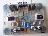
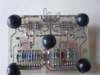
Sorry, that unit would teach you some things, but as a component matcher, it is useless. Useless and slow to use. The key here is that your pair must be running at the same temperature and current levels. This one requirement cancels most of the stuff out there. So much so that I finally had to design and build a jig that satisfies those requirements. No other type of instrument will work unless you can keep the transistors at a constant temperature (25 °C for example), and run them at the identical current levels. The thing I posted has been build a couple of times, and I finally put mine on a PCB because I used it too much and the perf board version wasn't happy about that. I have attached the images for this PCB.Nice suggestion on the transistor matcher as i was already considering this kit from Ebay:
Given that you are a keen listener, replace the tone section with a flat gain stage equal to the tone control circuit gain with the controls centered. Again, a nice little NE5532A would work quite well for this. Cheap, cheerful and easy. All you need to do is send a constant tone into the receiver with no speakers connected. Measure the level into the tone board, then for the output. Output / input = gain Set the replacement gain stage to test the same way, this can be calculated before the first resistor is touched. This way you are not touching the original tone controls so they can be replaced easily. Also, you could then put a switch to select between circuits and not suffer level changes. The NE5532 might just stay behind, you never know. This is a great way to learn, and the same building blocks can be used for more experiments.I am a very keen listener and one thing i noticed in my simple experiments that can make a huge difference in the overall spatial image is balance.
I hope you can pick up this pair of HP oscillator and THD meter. They will serve you extremely well.
-Chris
Attachments
@"Jooch"
In further support of using NE5532.
The supply rail for the tone control stage is 35.5 volts. The absolute working limit for most operational amplifiers is 36 volts. The NE5532 has a limit of 44 volts.
In further support of using NE5532.
The supply rail for the tone control stage is 35.5 volts. The absolute working limit for most operational amplifiers is 36 volts. The NE5532 has a limit of 44 volts.
A quick reply on the ceramic NP0 caps:
Anatech, if i could i would give you a hug right now. I found some of those NP0 (Philips) caps in the parts bin on VCR circuit boards.
Upgrading those ceramics fixed a long standing annoyance i have been trying to solve for years, but as others i never suspected ceramic caps to have any part in that.
With the NP0 caps harsh sounds in the high range practically disappeared, violins, flutes and piano sound very airy and clear.
Thanks again Anatech for solving that mystery for me.
PS: I replaced C5 (1200pf) with 1500pf. Would that be an issue?
@Jooch,
I think you could be more specific. There is more than one C5 in this equipment.
From the tone of recent posts it seems you have cleared the original faults and this is now an upgrading exercise rather than a repair job. If so, it is not clear what the causes were and how those were fixed. If not, which of them is still outstanding?
The repair information is something that ought to be shared - go on record where it can be observed by others now or in the future. There has been a lot of input to your repair.
Last edited:
Hi jooch,
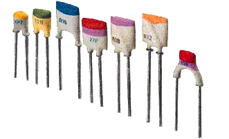
Well, I can't tell from looking at the capacitors you have shown. Normally on the tan disc ceramic capacitors they would mark the top with a black band (black = 0). It "sounds" like you installed the correct ones. (sorry about the pun, don't know if it translates).
To run op amps, you would be better off to create a bipolar supply at +/- 15 volts from the main power supply. You can either go the super regulator way (CCS driving a shunt regulator) or a normal series pass design (standard voltage regulator). Don't use the three terminal regulators for this, although there is a high voltage LM317 (HV) version. Series or pass types can both be designed to be excellent - down to splitting hairs.
There may be other locations where an op amp improves performance. So making a power supply would serve those too. If you run with a single ended supply as suggested, you will need to create a 1/2 supply reference voltage that also forces coupling capacitors on the input and output side. The 1/2 V reference will be a regulated power supply. If you do that, you may as well regulate the raw 35 V supply. Now you are looking at two supplies, two capacitors each channel, and the same for any other op amps you might add in the future. I would just make a bipolar one.
The other value of capacitance will shift the x-over frequency a little. For your good build, get the correct value. I guess this change was worth while then? 😉 Do the same thing for power amps, phono amps and anything else you listen to. Same for the power supply regulators.
-Chris
Would you please point out what exact parts you are using? Here is a link to Murata's capacitors. http://www.murata.com/~/media/webrenewal/support/library/catalog/products/capacitor/mlcc/c02e.ashx
I don't use these, but I feel uncomfortable with what I think you are using.
............
anatech,
Thanks for the catalog but it was easier for me to link to the exact part. This is the part that I got for bypassing the larger resistor in the NFB loop. I have had these for a while, am in no hurry and do not have to use this part. Murata 10pF MLCC C0G from Mouser.
Other than rated voltage and the fact that it is ceramic, is there something about this part that you don't like? Do you feel that MLCC is not ideal for this type of duty?
Among ceramics, type would you prefer for NFB, Miller, etc?
thank you
Last edited:
Hi roger2,
Ah-ha! Many thanks for the link. Now that I can see what this part is all about, I don't have any problems with it at all. Go ahead and use it.
Normally I would prefer to use a disc type NP0 / C0G ceramic, but more the polystyrene where there isn't heat, polypropylene or Teflon. Basically all "low-k" dielectric types. Silver mica is another really good type to use, even in the heat. So you can see there are a few factors that might influence the capacitor used. If you have a non-zero temperature co-efficient, high k ceramic in there, any plastic based capacitor will be an amazing improvement. Some amplifiers aren't good enough to warrant the more expensive capacitor types unless you intend to change a lot of things because you love the way it looks. But you can certainly improve an amplifier inexpensively (save your labour).
-Chris
@ jooch
Apologies for my repeated intrusions into your thread. From this point I will continue to watch silently from the sidelines. Wish you continued success with your project.
@ anatech
I appreciate the confirmation on the part selection. I am very cautious because I do not know how to use a scope to check for oscillation, clipping, etc and would not feel comfortable using a different type of cap for that reason. Things that go on above audible frequencies frighten me 😱
Here is the restore thread for the amp that I have been inquiring about. The amp is working perfectly and sounds great, and will not be on my bench for a while. No doubt there are many things that you would have done differently (or not done at all), but I am not seeking (further) advice on the project. The link is purely for your amusement should you be interested. If you have comments please PM so I can keep my stuff out of jooch's thread going forward.
Thanks again...
Hi jooch & roger2,
I may be wrong on this, but I think you were touching on topics of interest in general. Some of your questions may have guided others, including jooch with his projects. With that in mind I answered your questions as well.
A sure sign your amplifier might be oscillating would be the output zobel network smoking! In truth, this might be the first clue, although oscillation is pretty severe to do that. With an oscilloscope on the output with either no signal or some signal, a fat trace is a good indication you have oscillation (scope set at the normal 0.5 msec / div). With higher output levels, the trace might be fat, or only fat on the positive or negative extremes. All these things indicate possible oscillation. If you are playing music from a CD or other clean source, and you hear a "dirty" hum, that might be oscillation too. It would be better to have checked the amp on the bench with an oscilloscope to confirm the amplifier is stable before discovering this in your living room. Tweeters that stop working when the music is never turned up high is another sign of oscillation.
Question. What do they call a low frequency oscillation? It has a funny name.
-Chris
.........
Question. What do they call a low frequency oscillation? It has a funny name.
-Chris
motorboating?
- Status
- Not open for further replies.
- Home
- Amplifiers
- Solid State
- Modify bias circuit AKAI AM-2450