It is possible that what you need is a change of guitar, Fender to Gibson, or vice versa, or even different strings..
Fenders are famous for a thinner sound.
You will get a fatter sound with a Gibson.
I own a Peavey Patriot and it is somewhere between a Fender and a Gibson.
Billy Gibbons quotes BB King regarding how "hard" he (Billy) is playing and recommends "ultralight strings".... https://www.youtube.com/watch?v=UkzofCTa5SE pretty cool vid if you haven't seen it. Love his Magnatone indeed. How's that for a "sound" he he.
Thanks counter culture. I am definately not as good of a player as I would like to be. I am a bit self consious and I usually don't hit the strings hard enough. So to some extent I am looking for something that doesn't illuminate my mistakes. There's no problem with my guitar as I play an American deluxe tele.
I know my equipment is not what will make me sound good, but I am coming close to the sound I am looking for and thus this thread. So, I'll just keep working to get closer to the sound that I'm looking for with all of the help I am getting.
I know my equipment is not what will make me sound good, but I am coming close to the sound I am looking for and thus this thread. So, I'll just keep working to get closer to the sound that I'm looking for with all of the help I am getting.
Caution: The power amp section is using the heaters of V1 and V6 for cathode bias resistors. This is an old technique to provide "Free" DC Heaters to these tubes.
The power amp section needs very little work:
- to improve overdrive performance add 22K or even 47K grid stop resistors on each 6V6 grid 1.
- Reduce the feedback by changing R41 and R72, I would start by doubling these these resistors and halving the caps across them but you might want to go further later when you get to listen to it.
Strip the circuitry around the phono preamps, V1 and V6, and rebuild these as guitar preamps, note that you won't be able to run the amps without V1 and V6 in place because of the biasing method described above. You will also NOT be able to change these tubes to anything which does not use a 12V 150mA heater, that is, 12a_7 types will have to be used.
That should be enough to get it going and you can make further changes to suit once you've had a listen.
Cheers,
Ian
If I add grid stop resistors to the 6v6 tubes will I need to lower the value of the grid leak resistors?
No. And while you are at it it is good practise to add 1k screen stoppers to the screen of each power tube. And a grid stopper to the grid of each cathodyne phase inverter.
Stopper resistors should be added directly to the appropriate pin of each valve socket.
Google the valvewizard and do some reading up on these and my original suggestions.
Stopper resistors should be added directly to the appropriate pin of each valve socket.
Google the valvewizard and do some reading up on these and my original suggestions.
"Caution: The power amp section is using the heaters of V1 and V6 for cathode bias resistors. This is an old technique to provide "Free" DC Heaters to these tubes." Ouch, I knew Bell had something "advanced" in their design. Well their could be a way around this by measuring the current bias in place with the 1 ohm resistor inserted on the cathode, then install the correct resistor for the same bias. The OP did mention that he wanted to try a 6SL7 in the switched input pre-amp section.
Good catch on the old "free DC" trick. The schematic I have not saved ...yet, too small to read everything.- Doug
Good catch on the old "free DC" trick. The schematic I have not saved ...yet, too small to read everything.- Doug
Question 3.)
What are the implications of the "free dc". Does it only affect me if I want to change v1 and v6 tube types?
I am just starting to read up on biasing. I've spent most my time learning the signal path and the components directly involved. But I'm moving deeper now... On to biasing🙂
I've got my new e-caps in place and am ready to do some testing.
The "Free" DC Heaters thing has a number of implications.
First those heaters are rated at 12V @ 150mA (all the 12a_7 tubes have this rating). They are wired common to the 2 output tubes and so the 6V6s need to idle at 75mA each for V1 and V6's heaters to be properly powered. That idle current in the 6V6s is a bit hotter than you would normally see. Power Amp biasing is therefore deap Class AB, verging toward Class A. To keep power tube dissipation under control you will also see that the tubes are running lower B+ than you generally see.
The other implications are for modification - the power transformer almost certainly does not have sufficient heater winding current capability to convert V1 and V6 to normally wired heaters.
This scheme is just a smart way to take the "waste" heat which would normally be dissipated in the output tube cathode bias resistor and do something useful with it.
Gains are smaller/cheaper power tranny and the benefits of DC heaters in the high sensitivity part of the circuit (the phono preamp).
Note that the power tubes have to be normally heated to get the current flowing to get V1 and V6 heaters working. Back "in the day" the tech college instructors used to love giving out a circuit where the power tubes own heaters were wired as cathode bias resistors for the power tubes themselves and they would ask why won't this work? We would all analyse the circuit to death and miss the "bloomin'" obvious, the power tubes can't start conducting without heater power which in this quiz circuit you can't have until the tubes start conducting. No Chicken - No Egg ( or v.v.)
Cheers,
Ian
Just like steam re-use, send it somewhere else to do work before it's vented.
PPDB- Simply install another 3 amp, 6.3 volt filament XMF. On biasing, you need to figure Power Math. Volts (B+) x the amps (Milliamps across the 1 ohm resistor), so when a 1 ohm resistor is installed in the cathode string (between ground & the existing resistor already in place) and measure across it, the millivolt (DC) reading actually converts directly to milliamps. Take that number and multiply the measured plate voltage (to ground) will equal a power number in watts, or milliwatts. IxE=P so from a tube data sheet, find the "Class A" (perhaps would be a starting point), then look at whats called "Max Plate Dissipation", it will be given in "Watts", a number not to exceed.
This is how to know what exactly the "Max Bias" is and how to measure it. Gingertube mentioned that the B+ was slightly low on this amp. Since the 6V6 bias is grounded through other heaters (tubes) you will have to hunt around to measure what you already have on the 6V6 tubes, then with a replacement resistor (I would guess a 330 ohm to a 220 ohm 5 watt should be ok), start w/ the 330. But you should fully understand what the "Bias" adjustment is all about. When the plate voltage goes up, the current milliamp measurement goes down (ans still have the same overall power operating point) & vise versa. Better to know what your doing before you simply throw parts at something. As far as the "used to be biased from this now old free DC circuit" with the pre-amp tubes, you will have to re-install them, sort of say. But this is your chance to get your pre-amp section done right. Go slowly & ask alot of Q's, hopefully we will spend more time instructing you than confusing you, all along everyone is always learning 🙂-Doug
Last edited:
Thanks for the comments! I have question but I will hold on to them for now.
Before I go farther, there is a moderate amount of hum that I would like to tame.
These are the factors:
...moderate hum that increases with the volume control
...the hum gets worse when I wave my hand over v6 and to a lesser extent over v5(this is with the amp upside down and with the chassis open.)
...the hum goes away when I touch the first bypass capacitor c40.
...the hum gets a little better when I close the chassis.
Question 4.)
Are there any suggestion as to a solution?
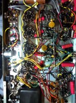
I will post a picture of the wiring... I've since replaced the large c4 cap...
The first thing I am going to do is change the cap. However i have yet to read that a bad coupling capacitor could cause hum...
Before I go farther, there is a moderate amount of hum that I would like to tame.
These are the factors:
...moderate hum that increases with the volume control
...the hum gets worse when I wave my hand over v6 and to a lesser extent over v5(this is with the amp upside down and with the chassis open.)
...the hum goes away when I touch the first bypass capacitor c40.
...the hum gets a little better when I close the chassis.
Question 4.)
Are there any suggestion as to a solution?
I will post a picture of the wiring... I've since replaced the large c4 cap...
The first thing I am going to do is change the cap. However i have yet to read that a bad coupling capacitor could cause hum...
Attachments
It could be the power supply. Normally this is the 1st place to start. Have you measured the AC on the DC B+ supply yet? What was the DC & AC value? Good to know the ratio also.
Are there any inputs not used and "open" or are they grounded as they should be?
Are there any inputs not used and "open" or are they grounded as they should be?
Last edited:
The hum has been removed🙂
I was only testing one channel at a time and that left one channel open. Should have known that one...
After shorting out the second input, there was still a small amount of hum that was eliminated by bending c15 and c40 so that they were nearly up against the chassis cover.
Doug...
Question 5.)
Can I leave the biasing scheme the way that it is or will it cause problems for me down the road?
Also
Question 6.)
I couldn't seem to measure the ac on the b+. My meter just kept bouncing around. What are the reference points I should use to measure this reading and how will this reading help me?
Question 7.)
I did get an ac reading of 4v across r73 (the first big b+ step down resistor). I expected it to be 0 just like the ones to follow. Is this normal?
Thanks!
PPDB,
Can I leave the biasing scheme the way that it is or will it cause problems for me down the road? Why I'm talking about installing the 6V6 bias resistors & re-installing the pre-amp tubes is remember these pre-amp tubes' heaters are the bias resistor for the 6V6s. I was discussing about the installation of a 1 ohm resistor at the cathode in series with your now in place circuit as to measure the current (millivolt drop) which will be measured in millivolts which w/ a 1 ohm resistor will directly correlate to a milliamp value on your DVM (digital volt meter). This value times (the math) x the measured plate voltage = your power or watts. Now reading from your tube data sheet in the class "A" operating mode (good place to start) will give you a guide to how much or how "hot" your tube is running allowing you to understand how much distortion, or how clean, including expected lifetime of the tube your in charge of. ....so this "biasing" deal is only important IF you decide to change out a 12 volt filament for a 6 volt, say 6SL7 pre-amp tube.
I couldn't seem to measure the ac on the b+. My meter just kept bouncing around. What are the reference points I should use to measure this reading and how will this reading help me? Good question.
I did get an ac reading of 4v across r73 (the first big b+ step down resistor). I expected it to be 0 just like the ones to follow. Is this normal? This is a good place to categorize the B+ AC component on the DC line as would most any place for your probe in the supply. I recommend the "Mini Clip" that will stay connected and is very small with hardly any exposed metal.
With all older electronics as you most likely already realize, it's the capacitors that degrade over time & temperature. They keep the DC up & the AC down. AC can live on a DC line. It creeps in from non-optimum wiring (as you have already found) and from aged capacitors. Fresh caps in a well designed DC supply should be well below 1 volt (AC) as read typically on most B+ supplies of say 400VDC under load. So perceived noise could be hiss, or hum or both. If you have not changed the power supply filter caps, I would recommend that you do. The older ones I used to use as explosive devices blowing up stuff when I was much younger. The design these days is to have a "vent" plug, however the older units like yours may fail & explode. Follow up measurements of the AC on your B+ supply under load & operating. Of course these will be fluctuating values, you will need to focus on peak & average readings, but should not exceed "peak" over a volt at worse case. The newer 47microfarad/450 volt are cheap and very small & are a quick install. Simply leave your old cans in place (if you like) , short them across the pins & to ground, and use the singles. $1.60ea from Mouser here in Texas. I can give you the link in my next reply.
Here is the Mouser Electronics link EEU-EE2W470 Panasonic | Mouser
or
B43041A5226M000 EPCOS | Mouser
The latter 10UF caps I like to use 2 in series & enjoy the now "900 Volt" rating. At 60 cents each you can really do good things, and they do have the vent cap so no explosions expected, only a small puff or hiss. Don't ask me how I know.....
Also your level of tech skills will be tested IF you consider yourself a novice as High Voltage is present my good man. Be sure and measure where you know the danger may exsist.....
Question for you, so do you have old supply caps? Time for a filter"re-cap"? The AC coupling caps only handle your signal, normally alright in the case of trouble shooting hum & other "old amp start-up" issues.
Good luck - Doug
Last edited:
Yes I have replaced the old supply caps. I replaced them with two 50/50uf 500v JJ can caps. I replaced those along with c4 before doing any testing.
I don't feel confident enough to start changing whole sections of the circuit, so I'm going to leave the 12ax7s in place. This way I can make small adjustments on the way in the direction of the sound I want. Then I will see what I end up with.
So...
I'm going to add resistors to the power amp section as described above then I am going to change some cap values to see what I get.
So...
I'm going to add resistors to the power amp section as described above then I am going to change some cap values to see what I get.
Yep. Get it sounding good with the Pod into the Aux inputs first.
Save modifying the earlier stages for direct guitar input for later.
Crawl before you walk etc.
This amp will give you projects and learning for years. Good score.
Cheers
JimG
Save modifying the earlier stages for direct guitar input for later.
Crawl before you walk etc.
This amp will give you projects and learning for years. Good score.
Cheers
JimG
Ok. I have installed a three prong power cord for safety and am not ready to move on to the installation of screen and grid resistors on the output tubes.
Question 8.)
The screens of all output tubes are connected to the 350v supply in series. Where should I place the screen stop resistors with the tubes wired this way? (The phase inverter tubes also get their 350v supply by way of a connection to the screen of one of the output tubes.)
Question 9.)
The grid leak resistor and the coupling cap are both connected right to the grid of the output tubes. Are there any tricks to adding grid stop resistors to this setup? I guess I could try to add a terminal strip next to each tube, but that would be a lot of work. Maybe I will just solder the glr lead to the cap lead and then connect the new resistor to this joint and the tube grid. I don't know if there is any other options...
Thanks for the help... I'm waiting for these resistors to come in the mail and then I will install them.
Before question 8 and 9...
After installing the three prong cord, I have a loud buzz that is not affected by the volume control. If I lift the ground, the buzz goes away. (I connected the black/hot to the fuze and switch, and the white/neutral straight to the transformer, and the green/ground bolted to the chassis.)
Question 10.)
Should I keep the ground lifted or is there a problem somewhere else that I need to solve?
- Status
- Not open for further replies.
- Home
- Live Sound
- Instruments and Amps
- Modify Bell 3030 into a stereo guitar amp project