Hi! Everybody, I'm now using a modified ColdAMP SPS80 to drive 2-channel UcD400AD, and the result is positive!! Transparent, deep bass and sweet sound that I can found after modification done!
ColdAMP SPS80
Layout
Modified the output cap to 4700uF/63V Jensen 4-poles Audio Grade E.Cap
Custom made back panel, WBT 720.12 signature series used
Jensen 1.0mm, 1.5mm Silver wire used for wiring
WBT 4% Silver Solder used
Jensen 4-poles E.Cap
The centre one is the Class-D power amp, Clone ProAc R3.8 and LCY Ribbon super tweeter!!
Now, I'm confusing the connection of the Jensen 4-poles E.Cap.
I found that in the Jensen's Web site, different kinds of connections of the 4-poles E.Cap, anyone know that which connecting method is the best?
My connection now is only parallel two 4700uF/63V in one side, + IN connect to the + side of C6/C7¡A- IN connect to the - side of C6/C7, + OUT and - OUT connect to the other cap's + IN and - IN, and finally the + OUT and - OUT connect to the + side and - side of C8/C9.
Is a best result given out in this kind of connections??
Thanks for any comment!!
Best Regards
Kenneth Lau
An externally hosted image should be here but it was not working when we last tested it.
ColdAMP SPS80
An externally hosted image should be here but it was not working when we last tested it.
Layout
An externally hosted image should be here but it was not working when we last tested it.
Modified the output cap to 4700uF/63V Jensen 4-poles Audio Grade E.Cap
An externally hosted image should be here but it was not working when we last tested it.
Custom made back panel, WBT 720.12 signature series used
An externally hosted image should be here but it was not working when we last tested it.
Jensen 1.0mm, 1.5mm Silver wire used for wiring
An externally hosted image should be here but it was not working when we last tested it.
WBT 4% Silver Solder used
An externally hosted image should be here but it was not working when we last tested it.
Jensen 4-poles E.Cap
An externally hosted image should be here but it was not working when we last tested it.
The centre one is the Class-D power amp, Clone ProAc R3.8 and LCY Ribbon super tweeter!!
Now, I'm confusing the connection of the Jensen 4-poles E.Cap.
I found that in the Jensen's Web site, different kinds of connections of the 4-poles E.Cap, anyone know that which connecting method is the best?
My connection now is only parallel two 4700uF/63V in one side, + IN connect to the + side of C6/C7¡A- IN connect to the - side of C6/C7, + OUT and - OUT connect to the other cap's + IN and - IN, and finally the + OUT and - OUT connect to the + side and - side of C8/C9.
Is a best result given out in this kind of connections??
Thanks for any comment!!
Best Regards
Kenneth Lau
Hi,
Nice layout. I like that case, alot, where'd you get it? Solide silver wire?? Whate gauge is used for the supply?
It looks like there might be additional linear regulators for an aux supply on that... If so I'd put them to use!
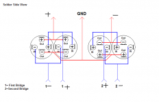
The way you have them adds the ESR. Wire your Jensen's like so:
Nice layout. I like that case, alot, where'd you get it? Solide silver wire?? Whate gauge is used for the supply?
It looks like there might be additional linear regulators for an aux supply on that... If so I'd put them to use!
The way you have them adds the ESR. Wire your Jensen's like so:
Attachments
looks really nice! Congrats!
What was it like before the modification? Did you compare it with the linear PS?
What was it like before the modification? Did you compare it with the linear PS?
Placing these capacitors away from their mounting locations and attached with long and spaced wires is a great mistake, despite the placebo-inducting fancy look.
I would agree with eva on that. tremendous amount of pulsing current going through those long and skinny wires.
It's not only pulsating current, it's tht any LC output filter is ruined by adding series inductance to the capacitor, particularly with a wire-like antenna.
More so because they're four poles and I doubt the possibility of mounting them on the PCB at all.
Placebo aside, these caps sound incredible, to the extent it's likely worth a bit of increased EMI. Still, I'd at least twist the wires and it might do to try a ferrite clip or other common mode choke right up against the PCB, in the least.
I'd twist all the other wires too.
Now that I look at it more, I really have no idea why the T networks are jumping back to the PCB. Can you not just // them for each rail and then go straight to the amps off the caps in the most direct route possible?
Could probably also put the caps in front of the supply and shorten the wires all the way around, from the supply to the caps and from caps to the modules.
classd4sure said:Hi,
Nice layout. I like that case, alot, where'd you get it? Solide silver wire?? Whate gauge is used for the supply?
It looks like there might be additional linear regulators for an aux supply on that... If so I'd put them to use!
The way you have them adds the ESR. Wire your Jensen's like so:
But the output of the Coldamp SPS80 is +VCC GND -VSS, how can I connect the T-Network like your attachment??
la1209 said:
But the output of the Coldamp SPS80 is +VCC GND -VSS, how can I connect the T-Network like your attachment??
Easy enough.
Add another wire.
V+/GND (two twisted wires) and Gnd/-V (two more twisted wires). The output ground formed by the cap common just goes straight to the amp power ground.
I'd put the caps in front of the SMPS in order to them as close as possible, and all wires as short as possible.
Hi! ClassD4sure,
Would you mind to send me the photo of your connection??
I've try to connect the Caps like your suggestion, +Vin GND use a twisted wire connected to C7, and -Vin GND connected to C6, also the OUT+ & OUT - of the Four caps becomes the GND of the output.
But the red LED on after I turned on the main power
Thanks!
Hi,
A picture would be of little help, if you respected the polarities show in the diagram I gave you it should be OK. Give it a close double check that you didn't reverse one of the rails?
A picture would be of little help, if you respected the polarities show in the diagram I gave you it should be OK. Give it a close double check that you didn't reverse one of the rails?
Elco's pressure release.
Some elco's top side also used as pressure release when explosion occur by overheating. Placing elcos also shall consider to where the direction of explosion.
Some elco's top side also used as pressure release when explosion occur by overheating. Placing elcos also shall consider to where the direction of explosion.
classd4sure said:Hi,
A picture would be of little help, if you respected the polarities show in the diagram I gave you it should be OK. Give it a close double check that you didn't reverse one of the rails?
I already check all the polarities, and nothing wrong.
But also fail to power on!
I don't know why?
Could you mind to sen me a pic of the connections of your caps??
Thanks a lot for a kindly help!!
la1209 said:Thanks everyone help!!
My problems already solved, thanks a lot!
So what was it then?
Actually, now I connected the Jensen Caps like classd4sure suggestion. For the best performance, we should connect in this way!
And also, I found that the sound becomes more muscial and detail, a possible way to modifiy your SPS80 in a best result.
Now I am using 1.5mm Jensen solid core silver wire for the power paths and 1.0mm for the signal paths. Worderful result that I can found, transperant and powerful!
More, I also setup two set of linear power supply for the input buffer of the UcD400AD
🙂
Good stuff!
Please inform us where you made your error, others who may want to follow might like to know.
It's good that you don't require a picture now because for one thing I dont' have a camera and for another, I'm in the middle of re-wiring my own supply..
Glad the changes paid off for you.
Please inform us where you made your error, others who may want to follow might like to know.
It's good that you don't require a picture now because for one thing I dont' have a camera and for another, I'm in the middle of re-wiring my own supply..
Glad the changes paid off for you.
- Status
- Not open for further replies.
- Home
- Amplifiers
- Class D
- Modified ColdAMP SPS80