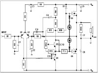
This is AN 948 circuit with modifications suggested by our group members as understood by me. I want to know whether they are correct?
1) Removed resistor from base of Q4 made direct connection.
2) Removed inductor from speaker output.
3) Added R14 ( 680 ohm same as R10) to base of Q6.
4) Added C8, C9 & C10. Kindly suggest values.
5) Added zener diode & diode as suggested.
Suggest zener diode value. The other diode i think is 1N4148.
Anybody built this circuit then let us have his experience about the circuit & any other modifications.
MP
Attachments
Okay,
1) This resistor was for High frequency stability in the VAS and this is now acheived by C9 wich shoud be 100pF. you have removed the R and bootstrapped it.
2) The inductor also helped HF stability and might not be needed with these Mods.
3) Gate resistor so that Q6 won't oscillate, this is fine.
4) C8 (10-100 pF) bypasses feedback R, Is this also for HF stability or to control HF oscillation? If so, I would only add if needed. C9 - 100pF. C10 AC bypasses the Vbe Multiplier for HF Crossover distortion I believe - 1uF or lower.
5) 12 - 20 V Zener depending on what you use as Q5 and Q6. It should be just under the Vgs breakdown voltage of these devices.
-D.
If i want to use the same circuit for subwoofer amp then which components i can omit.
Mahendra Palesha
Mahendra Palesha
As this circuit is pretty simple, I'm not sure that I would omit anything. Even if the intended use of the amp is for a subwoofer, it should still be stable at higher frequencies so that it doesn't oscillate which would be bad. I might omit C8 and C10 but not really anything else. I would probably replace R3 R4 and C3 with a constant current source as I think this might be quieter than the R4/C3 filter.
-D.
-D.
palesha,
please add an input capacitor (10µF) to avoid DC at the input, your speakers would appreciate that 😀
add two resistors of 47 ohm in series with the emitters of Q1 and Q2, to minimize the differences between these two transistors.
HB.
please add an input capacitor (10µF) to avoid DC at the input, your speakers would appreciate that 😀
add two resistors of 47 ohm in series with the emitters of Q1 and Q2, to minimize the differences between these two transistors.
HB.
- Status
- Not open for further replies.