Those resistors were there before, I was just suggesting the topology for ease of implementation. Without these resistors, the amplifier can only be compensated by the capacitance in the feedback circuit.Hennady Kovalsky - I see the emitter resistors added to the first differential. Have you checked the sensitivity to device variations in the second differential? I see very high gain for decent tracking between the complementary halves.
And you are right about the stability of the input stage.
It is also advisable to add resistors to the second stage, but I proceed from the task of modifying the finished board; these resistors are not there.
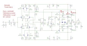
The 3rd stage of modification is the simplest and most significant - to replace the output transistors with vertical mosfets IRFP240/9240 (see attachment).
The pole is at 120Hz, the open loop gain is 90dB.
Replacing with vertical mosfets due to the asymmetrical limitation of half-waves of the sine wave with a large input signal, about 4 volts are lost. with mosfets, the limitation is symmetrical and 4 volts was used to bias and obtain the initial current for vertical mosfets. With them the limitation is symmetrical, maximum power 100 watts (4 ohms)
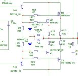
protection of vertical mosfets gates is to the scheme in the second attachment.
The pole is at 120Hz, the open loop gain is 90dB.
Replacing with vertical mosfets due to the asymmetrical limitation of half-waves of the sine wave with a large input signal, about 4 volts are lost. with mosfets, the limitation is symmetrical and 4 volts was used to bias and obtain the initial current for vertical mosfets. With them the limitation is symmetrical, maximum power 100 watts (4 ohms)
protection of vertical mosfets gates is to the scheme in the second attachment.
Attachments
Last edited:

And the thermals. Slight negative co-efficient (LED) of the CCS and the VAS. VAS is 4mA 0C ---> 3.95mA 30C.ostripper - You have avoided the tracking problem that complementary designs are susceptible to. 🙂
Ed
Some designs compensate after the IPS by making the EF stage negative Tc.
Being modular , I wanted LIN types and complementary to have the same behavior.
Hennady's designs would have to built and run to tweak the thermals. Biggest drawback with complementary designs (besides tracking).
PS - I'm measuring <50uV offset on all 3 of my amps. No servo in the audio path !
OS
Last edited:
C9 VAS----> NFB lead comp. works good. Retains margin - better than "shunt".is a more “calm” frequency compensation for the Tweak 2 step option
OS
Hello, I am very sorry to intrude on your conversation, but I would be extremely grateful if you could send me a quality copy of the "Shema for Mod Henk" amp schematic. I just bought the circuit boards but the seller doesn't offer the schematic.no problem, see attachment
I also added the original version (on a piece of paper) according to which this version of the amplifier was made.
modifications:
1. the middle point of the pre-output repeater resistors was disconnected from the common output - this reduced distortion by 4 times
2. progressive compensation has been introduced - this is the input filter R1/R4C2 and the load circuit output to the voltage amplifier R24C8 - these two circuits are included as coefficients of the equation of state variables, because when increasing the linearity of the input stage, it is necessary to limit the input spectrum (using a progressive filter) without a significant change in phase - this is the only way it works and these concepts should not be separated, because this contradicts the meaning of this progressive compensation.
The purpose of the correction (progressive compensation) is to increase the linearity of the input stages, which determine the sound quality of the amplifier
3. It is planned to re-solder VT5VT6 (circuit on a piece of paper) as Q3 Q8 - this will stabilize the operation of the input differential stages at large signal values at the input of the circuit, which will reduce distortion more in 3 times.
P.S. Post No. 12 shows how an output stage in class B was able to reduce distortion by 30 times without changing the compensation circuits - this is modeling nonsense, and has nothing to do with the actual sound, so this option is not considered, but in the model everything looks good in terms of distortion.
- Home
- Amplifiers
- Solid State
- Modification of a simple amplifier with symmetrical topology