I am currently playing around with various enclosures in Hornresp to get my head around it.
Does anyone know if it is possible to model a metronome style speaker in Hornresp? I havent found any tutorials which mention it and I cant work out how to model the port in the Hornresp parameters.
Is it possible? Any hints?
Does anyone know if it is possible to model a metronome style speaker in Hornresp? I havent found any tutorials which mention it and I cant work out how to model the port in the Hornresp parameters.
Is it possible? Any hints?
Yes, working on it, but I’m having trouble getting a good agreement with MJK’s MathCad software’s sim for a Fostex FF165WK, which I find strange based on doing some other type alignment comparisons that compared close enough for me, so querying the HR cognoscenti: http://www.diyaudio.com/forums/subwoofers/119854-hornresp-106.html#post3840976
GM
GM
GM,
Can you point me to the dimensions of the cabinet for the FF165WK? I have a model and want to check against your baseline case.
Thanks,
X
Edit: just clicked on your link and see the dimensions.
Can you point me to the dimensions of the cabinet for the FF165WK? I have a model and want to check against your baseline case.
Thanks,
X
Edit: just clicked on your link and see the dimensions.
For the FF165WK in a Met prescribed as:
L = 55"
SO = 5"^2
SL = 90"^2
zdriver = 30"
zport = 53.25" [actually exits out the bottom]
rport = 1.5" [3" dia.]
Lport = 2.5"
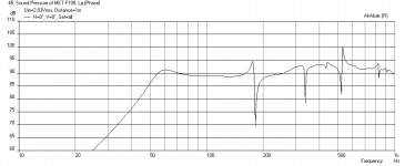
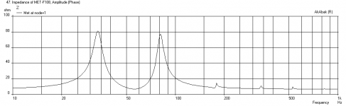
I get a 55 Hz impedance dip too with Akabak. I am assuming the port is located 55 in at the base and not 53.5 in.
L = 55"
SO = 5"^2
SL = 90"^2
zdriver = 30"
zport = 53.25" [actually exits out the bottom]
rport = 1.5" [3" dia.]
Lport = 2.5"
I get a 55 Hz impedance dip too with Akabak. I am assuming the port is located 55 in at the base and not 53.5 in.
Attachments
When a bottom firing vent is > baffle thickness, then its location is however high up inside it is.
I wonder why AkAbak's resonant structure is so far off.
GM
I wonder why AkAbak's resonant structure is so far off.
GM
Yes, the resonant freq should not be that far off from the MJK simulation. I have damping in the top above driver but shouldn't change freq that much. It might have to do with volume of speaker. I have chosen some values for depth vs width based on the CSA provided but depending on how deep or shallow a speaker is for a given CSA the volume will be different. Maybe make it square cross section (depth and width the same) to maximize volume? In MJK and HR I wonder if CSA is round square or rectangular? Because my model uses actual width and depth of top and bottom.
Yeah, sure surprised me since his is normally close enough to HR's. Then again, I'm using his first [freeware] WS that actually simmed the vent location as opposed to it being at the same point as the driver, so what does his current WS sim?
GM
GM
Yes, the resonant freq should not be that far off from the MJK simulation. I have damping in the top above driver but shouldn't change freq that much. It might have to do with volume of speaker. I have chosen some values for depth vs width based on the CSA provided but depending on how deep or shallow a speaker is for a given CSA the volume will be different. Maybe make it square cross section (depth and width the same) to maximize volume? In MJK and HR I wonder if CSA is round square or rectangular? Because my model uses actual width and depth of top and bottom.
Sound is round', so CSA = net circular area regardless of shape, driver encroachment, ergo net Vb should be identical in both MathCad & HR's theoretically ~infinite limits. If it's not in AkAbak, then you're using the wrong dimensions. IOW, actual build dims should ideally take all this into account.
Anyway, it's obvious that MJK has a real world acoustical resistance factor included as shown by the damped harmonics, but what stymies me is they still line up well in HR, so can't think of a reason why its fundamental is so far off.
GM
Hi,
FYI: IMO,The similarity between HR and the correspondingly correct MJK program is very good:
http://www.diyaudio.com/forums/subwoofers/119854-hornresp-422.html#post3841763
b🙂
FYI: IMO,The similarity between HR and the correspondingly correct MJK program is very good:
http://www.diyaudio.com/forums/subwoofers/119854-hornresp-422.html#post3841763
b🙂
GM,
You are right, CSA is independent of shape, I was mistaken. My Akabak script takes the actual width and depth and converts it to CSA for use in the actual acoustic element. I see that David McBean and Bjorno both get something higher in the fundamental freq compared to the MJK WS.
X
You are right, CSA is independent of shape, I was mistaken. My Akabak script takes the actual width and depth and converts it to CSA for use in the actual acoustic element. I see that David McBean and Bjorno both get something higher in the fundamental freq compared to the MJK WS.
X
Yeah, sure surprised me since his is normally close enough to HR's. Then again, I'm using his first [freeware] WS that actually simmed the vent location as opposed to it being at the same point as the driver, so what does his current WS sim?
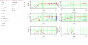
Possibly some variability with what driver parameters are used / assumed? For the attached, I stuck Qe, Qm, Re, B*L, Fs & Sd into WinISD, let it calculate the rest, & used those. Left column sans damping, right column assuming throat, back & 1 sidewall damped to the bottom. The graph scales are larger in the current sheets, so a little visual difference creeping in there.
Attachments
Last edited:
Wow, it seems like I sparked a bit of discussion!
It sounds like the conclusion is that the design parameters entered into the different software packages is where the slight discrepancy arises, and otherwise the different packages agree?
In regard to my original post, the trick I was looking for was this:
A section 0.01cm long with negative taper which closes the horn section and allows us to create a port at the end.
It sounds like the conclusion is that the design parameters entered into the different software packages is where the slight discrepancy arises, and otherwise the different packages agree?
In regard to my original post, the trick I was looking for was this:
Code:
S3=580.64
S4=45.60
Con=0.01
F34=0.00
A section 0.01cm long with negative taper which closes the horn section and allows us to create a port at the end.
Does this look correct for a model of the FE126E Metronome?
Code:
ID=34.00
Ang=2.0 x Pi
Eg=2.83
Rg=0.00
Fta=0.00
S1=22.22
S2=87.19
Con=50.80
F12=0.00
S2=87.19
S3=248.31
Con=71.10
F23=0.00
S3=248.31
S4=20.43
Con=0.01
F34=0.00
S4=20.43
S5=20.43
Con=7.60
F45=0.00
Sd=65.00
Bl=5.14
Cms=9.99E-04
Rms=0.27
Mmd=2.99
Le=0.04
Re=7.10
OD=1
Vrc=0.00
Lrc=0.00
Ap1=0.00
Lpt=0.00
Vtc=0.00
Atc=0.00
Pmax=100
Xmax=5.0
Fr1=0.00
Fr2=0.00
Fr3=0.00
Fr4=0.00
Tal1=100
Tal2=100
Tal3=100
Tal4=100
Comment=FE126eN^2 Basic Metronome
~~~~~~~~~~~~~~~~~~~~~~~~~~~~~~~~~~~~~~~~~~~~~~~~~~~~~~~~~~~~~~~~~~~~~~~~~~~~~~~~~~~~
FILTER
    0.0    0.0    0.0    0.0    0.0    0.0    0.0    0.0    0.0    0.0    0.0    0.0
    0.0    0.0    0.0    0.0    0.0    0.0    0.0    0.0    0.0    0.0    0.0    0.0
    0    0    0    0
0.50.50.50.5
0.50.50.50.5
SSSS
1111
1111
2222
1111
111
000
~~~~~~~~~~~~~~~~~~~~~~~~~~~~~~~~~~~~~~~~~~~~~~~~~~~~~~~~~~~~~~~~~~~~~~~~~~~~~~~~~~~~For future reference, please save designs in HR's EXPORT folder, then attach the .txt file to the post, so folks can save them to their IMPORT folder, which auto loads it up as a new file to view/whatever.
Looks fine overall, though note that I changed S2 slightly, or rather HR did. Don’t know how you inputted the alignment, but to ensure best accuracy you must double click ‘Manual’ above the S2 slider in the loudspeaker wizard [LW] for it to auto adjust any discrepancy in the slope expansion contour, then save it.
Also, play with the new line damping option by double clicking ‘Apt’ to get ‘Fr’, then find the best overall driver location in the LW’s ‘Response/Chamber/Combined’ window and if it’s too low to the floor, then experiment with a taller and/or larger net Vb while maintaining the same throat area [S1] as you might find an alignment you like better.
Unfortunately, I haven’t been keeping up with all the latest HR updates and don’t know how to correlate its stuffing density to a particular material, though maybe there’s been some mention in HR’s monster thread: http://www.diyaudio.com/forums/subwoofers/119854-hornresp.html
GM
Attachments
- Status
- Not open for further replies.
- Home
- Loudspeakers
- Full Range
- Modelling a Metronome in Hornresp