Oscar, did I ever post the one where I made a phase plug for a ribbon and a waveguide?
I actually took a square ribbon, compressed the wavefront, with a circular exit.
There's definitely a video on YouTube, but I can't recall if I ever posted a thread or any measurements. It worked better than I expected it to!
If you're going to compress the wavefront of a ribbon, you might consider lining the compression chamber with a little bit of foam or polyfill. The reason, is because it will roll off the highs. This is a necessity in this type of design, because the pathlengths are difference.
This is one of those things where I really wish I had time to post a picture, but let me see if I can describe the dilemna:
With a waveguide, we want a flat wavefront at the throat. A ribbon is already flat. This creates a conundrum, if you're trying to make the throat smaller: some of the pathlengths are going to be unequal. The addition of foam or poly fill, on the edges of the chamber, will help reduce the impact of those unequal pathlengths. Basically the pathlengths which are slightly longer are attenuated by the polyfill.
Again, the BG ribbons use the same idea in their PDR ribbon. That's why the felt is there; it makes be beamwidth wider.
Having said all of that, I'm sloooowly moving into the Dan Wiggins camp of "why use a ribbon when a dome works so much better?" The only real advantage that a ribbon has, that I can see, is some added efficiency at very high frequencies.
I see your point. I'm not gonna go crazy with it. In fact, I used the term compression, when really it's not even that; I should have been more careful with my wording. It's more like extreme throat-matching.
Since this is an AMT and not a planar ribbon, or even a true ribbon, the outer edges are fixed, so the degrees of freedom are reduced on the outside perimeter of the folded diaphragm---they don't actually move because they're glued in place. My idea was to simply bring in the throat sides to cover the first fold on each side, and to come in closer top-to-bottom over the part that is actually glued to the plastic cassette that houses the diapragm (ie: no harm in covering a part that is immobilized by design in the first place).
Let me see if I can illustrate from a pic:
So basically, my next iteration will come in from the top/bottom and the sides where the orange "rectangle" lies, instead of to the edge of the semicircular openings on the Left/Right of the front-plate as it currently is.
Looks great Oscar. When are you going to tighten up the throat of your waveguide? I’d love to see the results.
Looks great Oscar. When are you going to tighten up the throat of your waveguide? I’d love to see the results.
I'm hoping within the next month.
The width of your diaphragm is going to set a limit on how high your waveguide will work.
That is not true. On magnetostats, ribbons and other large diaphragm drivers, you can implement a vertical 'divider' in the middle of the diaphragm which increases the upper limit of the waveguide/horn. You will find there are actually a lot of drivers that already use that, the first ones being around ~40 years old.
I'm not saying your project is hopeless, just warning that directivity is going to be uncontrolled above about 6khz-ish.
Also, if you'd like to read more about this phenomenon, check out some of my threads on ribbon tweeter phase plugs, and phase plugs in general. Fun stuff!
Like mentioned above, that's not necessarily the case. It will be a lot of fiddling and measuring though, taking a lot of time and prototypes.
The driver is not well suited for such a WG because of other reasons. The first problem is, the diaphragm or, to be more precise, the effective opening of the driver is not constant, it changes several times over the complete height. To have a perfectly working horn/WG, it would have to have an equal opening width at the horn throat. A WG will work to a certain degree but you won't be able to get a perfect shape or response and dispersion. It can ofcourse be acceptable but, like said, not perfect. There will be also resonances/reflections within the horn you'll have to fight because of the large (vertical) dimensions. You have to determine which compromises are acceptable, ie. dispersion vertically and horizontally.
The second biggest problem is your room. With a that large diaphragm, the vertical dispersion is already very narrow and extends the narrow field very much. To add a WG will increase that further. On the one hand you eliminate a lot of reflections of the ceiling and floor, probably also on a table or other furniture. That, in general, is a good thing. Your drivers below, according to your photo direct dispersing driver(s), do not have the same controlled disperson or near field extension like your huge AMT. The dispersion of the mids will be a lot wider, leading to an inhomogenous sound unless you've got a very big listening room with generous distance between the speakers and walls and about >~4m listening distance, where it starts to fit together again, that's the drawback of many large drivers/horns with narrow dispersion and great distances between the acoustical sources vertically. If you change the position (sitting/standing) it will sound a lot different, even a DSP can't fix that because it can't change the dispersion pattern/angle.
If you got low(er) expectations regarding the homogenity and room impression and maybe fixed listening point, you maybe find the compromises you have to take to be acceptable, many were disappointed though. Over the span of around ~20 years I tried to help four different friends to put their - pretty much similar - ideas into reality, one very large ribbon (I think it was ~70cm high), a 6-8 dome tweeter array and several array'd magnetostats among them. None of them found any of the WG or short array sounding the way they imagined or wanting it over a longer period of time. One of them went for a big (12") fullrange speaker, two settled happily for 'traditional' or modern horn speakers, one built a floor-to-ceiling line array with wide band speakers (sold it later though) and a subwoofer array instead.
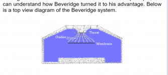
I think a Beveridge type lens in front will help
technical_details
scroll down until you see this picture
technical_details
scroll down until you see this picture
Attachments
I think a Beveridge type lens in front will help
That's not easy to build, that will become a real PITA with the asymmetrical front slots. And it will not help much because it's not a magnetostat like in the link, it's an AMT, the air between the folds would work like a compression chamber but with a way too high volume, working then as an unwanted lowpass.
Aside from that, the sound running difference isn't reduced, that causes interferences at the horn throat, leading to a jagged response.
I would add some nude midbasses to get down to 300hz and suspend them above the woofer box with the amt. Keep them away from walls and add other woofers to smooth out bass response.
I would not bother with a waveguide on these. Defeats the purpose. Use sound absorbers, positioning, and dsp delays to work out a good solution.
I would not bother with a waveguide on these. Defeats the purpose. Use sound absorbers, positioning, and dsp delays to work out a good solution.
- Status
- Not open for further replies.
- Home
- Loudspeakers
- Multi-Way
- Modeling Waveguides for AMTs