I am having trouble modelling an ideal Pull-Push center tap 8 ohms transformer with a 6.7k primary anode-anode impedance in LTspice.
Formula:
8*(Np/Ns)^2=7.6k
Thus, Np/Ns=30.82/1
Here are my LTspice schematic. Could someone please help me out?

Thanks
Formula:
8*(Np/Ns)^2=7.6k
Thus, Np/Ns=30.82/1
Here are my LTspice schematic. Could someone please help me out?
Thanks
Inductance too low? Seems typical PP iron has primary inductance in 10's or lower 100's of Henries, much higher than micro-Henries.
Try this: K1 L1 L2 L3 1.
And yes, microhenries are way too low inductances for that application.
And yes, microhenries are way too low inductances for that application.
Last edited:
I use the folowing sims for my single end and push & pull sims
http://forum.zelfbouwaudio.nl/download/file.php?id=65461
http://forum.zelfbouwaudio.nl/download/file.php?id=65461
An externally hosted image should be here but it was not working when we last tested it.
including series R and parallel C help get more realistic as well as the right K less than 1.0 to include leakage L - can then see more of the (high) frequency response
if you include the parasitics in the L def in LTspice you should check the box for them to be displayed on the schematic so people can see what your using
if you include the parasitics in the L def in LTspice you should check the box for them to be displayed on the schematic so people can see what your using
Last edited:


if you include the parasitics in the L def in LTspice you should check the box for them to be displayed on the schematic so people can see what your using
oops, doesn't look like there's a box for R, L, C - the V, Isource parts do have a "make information visible" check box
maybe a request to Mike?
certainly the schematic isn't adequate documentation with the information only visible when running LTspice and clicking on the component
so to share as a drawing documenting your circuit you would need to put the info in text comment lines
adding explicit Rseries, Cparallel works but LTspice claims the solver works better with the internal device spec'd parasitics
Last edited:
The inductance values for the Bassman are way too large 😉
What would be more realistic jazbo?
Thanks.
For the Marshall JTM45 (based on the Bassman), Hammond offers this replacement OPT. At 240V and 50Hz, they spec the input inductance at 136H (open circuit on secondary). I would presume that is across the full primary.
I'm curious why they rate the inductance at such a high voltage and low frequency? I'm guessing the rating at such a low frequency is important for low frequency drive considerations. Does the inductance increase with voltage? If so, why?
I'm curious why they rate the inductance at such a high voltage and low frequency? I'm guessing the rating at such a low frequency is important for low frequency drive considerations. Does the inductance increase with voltage? If so, why?
Attachments
I use the folowing sims for my single end and push & pull sims
http://forum.zelfbouwaudio.nl/download/file.php?id=65461
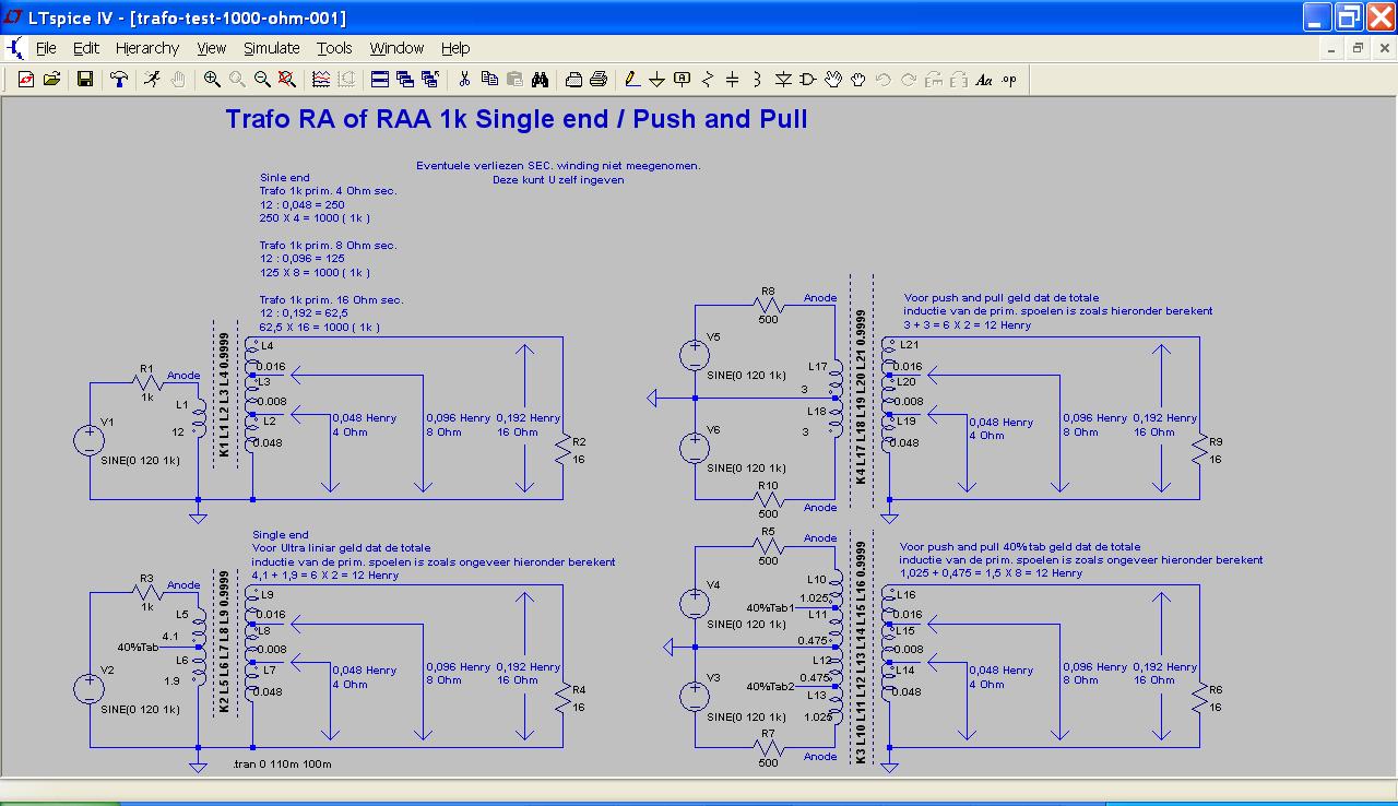
how to calculate the screen grid tap inductance (40%)?
> how to calculate the screen grid tap inductance (40%)?
40% is 0.4
Inductance goes with Square of turns.
So 0.4*0.4 is 0.16 of inductance.
The G2-P part of the winding is obviously 0.84 of inductance.
40% is 0.4
Inductance goes with Square of turns.
So 0.4*0.4 is 0.16 of inductance.
The G2-P part of the winding is obviously 0.84 of inductance.
> how to calculate the screen grid tap inductance (40%)?
40% is 0.4
Inductance goes with Square of turns.
So 0.4*0.4 is 0.16 of inductance.
The G2-P part of the winding is obviously 0.84 of inductance.
Also
60% is 0.6, so 0.6*0.6=0.36
Then, deff (*)
L1 = 0.16 L, L2 = 0.36 L
Then
L = L1 + L2 + 2 M
M = k √(L1 L2)
For k=1 (this was already assumed)
M = √(L1 L2)
Et voilà
L = 0.16 L + 0.36 L + 2 L √(0.16 0.36 )
Hint: Assume (*) as an approximation and make
k = √(1 - Lleak / L)
Last edited:
Try these:
Thanks to Robert Mclean
http://www.diyaudio.com/forums/tubes-valves/68767-spice-model-ul-output-transformer.html
http://www.diyaudio.com/forums/tubes-valves/181578-spice-transformer-model-spreadsheet.html
Regards
John
Thanks to Robert Mclean
http://www.diyaudio.com/forums/tubes-valves/68767-spice-model-ul-output-transformer.html
http://www.diyaudio.com/forums/tubes-valves/181578-spice-transformer-model-spreadsheet.html
Regards
John
> how to calculate the screen grid tap inductance (40%)?
40% is 0.4
Inductance goes with Square of turns.
So 0.4*0.4 is 0.16 of inductance.
The G2-P part of the winding is obviously 0.84 of inductance.
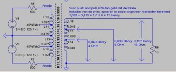
Thanks so much for that.... but still there is a confusion on it. ...I think the picture can be more clear. My question is:
L10 = 1.025, L11 = 0.475 and L15 = 0.008 is how to calculate it?
Attachments
Although I use TINA rather than LT Spice, I have always found that first you put in an ideal transformer, with the correct ratio.
Then you add an inductor of the real primary inductance across the primary of the ideal transformer. If you have measured the leakage inductance (measured at the primary with the secondary short-circuited) then you add two series inductors (assuming a P-P output in each half of the primary windings. You can of course improve the model by adding the values for the winding resistances and stray capacitances.
Doing things this way, starting with a perfect transformer model, you can see if the basic design is OK, and how much it degrades as the model is made more like the real thing.
- Status
- Not open for further replies.
- Home
- Design & Build
- Software Tools
- Modeling Pull-Push transformer in LTspice