I've been modeling 300B SET circuits in LTSpice for a potential build and am wondering what to make of the initial transient analysis results.
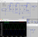
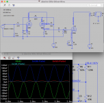
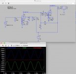
The 4 circuits I modeled use the Magnequest TFA-204 OPT, with the 300Bs operating at 350Vak/60mA and the 2A3 at 247Vak/60mA.
* Fi Primer 300B
* JE Labs 300B
* George Wright WPA 3.5 2A3
* Albertine 300B
The Fi Primer and JE circuits are based on the Sun Audio SV300B. The Wright WPA 3.5 is the basis for what I'm calling the Albertine 300B, an unmodified WPA 3.5 6SN7 stage with a 300B output stage dropped in.
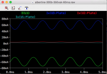
Screenshots of the schematics (which show voltage measurements at key locations) together with their transient analysis graphs are attached. The Sun-based amps are shown with a 0.25V signal while the Wright WPA is shown with a 2V signal and the Albertine with a 1V and 4V signal separately.
Some observations:
1. In the two Sun-based amps, any input signal voltage greater than 0.25V will send the amp into clipping. That means they have an input sensitivity of 0.25V (as far as the sim is concerned; real-world measurements may vary). Correct?
2. The two Wright-based amps have an input sensitivity of around 4V for the reasons stated above.
3. Does this mean that the Wright-based amps have more headroom, meaning they can take greater input from a line preamp without sounding strained?
4. The Sun-based amps with their maximum 0.25V signal produce current swings from about 0mA to 100mA. The Wright-based amps with their maximum 4V signal produce current swings from about 0mA to 120mA. Does that mean that the Wright-based amps are capable of more dynamic sound?
5. The Albertine with a 1V signal (see attached graph without schematic) swings from 42mA to 78mA. Does this mean it will be quieter at this input level than the Sun-based amps at 0.25V, all other factors being equal?
Thanks for any insight you might be able to provide on these sims. I'm still pretty new to all this and am trying to understand how the sims might translate into sound.
The 4 circuits I modeled use the Magnequest TFA-204 OPT, with the 300Bs operating at 350Vak/60mA and the 2A3 at 247Vak/60mA.
* Fi Primer 300B
* JE Labs 300B
* George Wright WPA 3.5 2A3
* Albertine 300B
The Fi Primer and JE circuits are based on the Sun Audio SV300B. The Wright WPA 3.5 is the basis for what I'm calling the Albertine 300B, an unmodified WPA 3.5 6SN7 stage with a 300B output stage dropped in.
Screenshots of the schematics (which show voltage measurements at key locations) together with their transient analysis graphs are attached. The Sun-based amps are shown with a 0.25V signal while the Wright WPA is shown with a 2V signal and the Albertine with a 1V and 4V signal separately.
Some observations:
1. In the two Sun-based amps, any input signal voltage greater than 0.25V will send the amp into clipping. That means they have an input sensitivity of 0.25V (as far as the sim is concerned; real-world measurements may vary). Correct?
2. The two Wright-based amps have an input sensitivity of around 4V for the reasons stated above.
3. Does this mean that the Wright-based amps have more headroom, meaning they can take greater input from a line preamp without sounding strained?
4. The Sun-based amps with their maximum 0.25V signal produce current swings from about 0mA to 100mA. The Wright-based amps with their maximum 4V signal produce current swings from about 0mA to 120mA. Does that mean that the Wright-based amps are capable of more dynamic sound?
5. The Albertine with a 1V signal (see attached graph without schematic) swings from 42mA to 78mA. Does this mean it will be quieter at this input level than the Sun-based amps at 0.25V, all other factors being equal?
Thanks for any insight you might be able to provide on these sims. I'm still pretty new to all this and am trying to understand how the sims might translate into sound.
Attachments
-
 fi-primer-300b-350vak-60ma-0.25v-graph.png133.8 KB · Views: 789
 -
 je-labs-300b-classic-350vak-60ma-0.25v-graph.png122.7 KB · Views: 763
 -
 albertine-300b-350vak-60ma-4v-graph.png138.6 KB · Views: 668
 -
 albertine-300b-1v-graph.png48.5 KB · Views: 614
 -
 wright-wpa-3.5-247vak-60ma-2v-graph.jpg115 KB · Views: 692
Last edited:
1. In the two Sun-based amps, any input signal voltage greater than 0.25V will send the amp into clipping. That means they have an input sensitivity of 0.25V (as far as the sim is concerned; real-world measurements may vary). Correct?
2. The two Wright-based amps have an input sensitivity of around 4V for the reasons stated above.
3. Does this mean that the Wright-based amps have more headroom, meaning they can take greater input from a line preamp without sounding strained?
Headroom is not the same thing as sensitivity. The versions that clip with only 250mV of input signal are not meant to be used with a preamp-with-gain. Put input jacks, an input selector and a volume control on it and call it an 'integrated amplifier.' The versions that clip with 4V input signal *require* a preamp-with-gain. Two different design goals.
--
Gotcha. Thanks. That's what I figured but wanted to make sure I was reading this right.
Added here is the WE91A adaptation by Joe Roberts in the first issue of Sound Practices, also using the TFA-204 and a 0.5V input signal. I had to up the 300B cathode resistor from 880R to 1.25K to get the plate current down to 60mA, but it looks good. 300B is at roughly 350Vak and the 6SJ7 at roughly 150Vak.
JonSnell: I hear you. Nothing beats experience, but modeling for a newb like me is a way to learn more about basic tube operation before investing in the expensive components needed for running 300Bs.
I've built 2 half-kits (Tubelab SE 300B, VTA PH16) and one from-schematic preamp (VTV octal line stage) so far. I'll be selling the Tubelab, which I really like, to invest in parts for the 300B mono blocks. Since the four 300B circuits I've now posted here use octal input and rectifier tubes, I can use the same iron and just swap in different caps and resistors to try all of them.
I would think a pair of 750V PTs like the hammond 274X or BX would work for all of these circuits.
Question is how to model the PS in PSUD2, or better yet LTSpice, to account for the different taps going to the input and output tubes.
Attachments
Following, IMO you are on the right path..
Recommend you also consider 2 stage amps (driver and output tube) beyond WE91 and it you are up for the challenge IT. (Lundahl makes some good ones for not too much money)
Recommend you also consider 2 stage amps (driver and output tube) beyond WE91 and it you are up for the challenge IT. (Lundahl makes some good ones for not too much money)
I know -- I want to try it all, but baby steps. Might as well learn what I can from the 2-stagers and then go for 3-stage all tube or IT designs.
I also want to make a Wheatfield HA-2 headphone amp and restore a Harman-Kardon Citation V. Need another job to support this growing obsession.
I also want to make a Wheatfield HA-2 headphone amp and restore a Harman-Kardon Citation V. Need another job to support this growing obsession.
I made a breadboard on which to build the modeled the Fi Primer and JE Labs circuits (interested members may follow some of that in this thread: Modeling Fi Primer 300B with LTSpice).
Now I'm about to try an experiment, which is the front end of a George Wright WPA 3.5 (a 2A3 unit) but with a 300B at the output stage. Since George used 5Y3's in his 2A3 and 300B amps, I wanted to try the same, but he did mono blocks wheres this is a stereo pair with one PT and one rectifier tube, but with one PS rail per channel.
I calculate about 160mA total circuit draw from the 300Bs and 6SN7s of both channels. The RCA datasheet for the 5Y3GT says max DC output current of 125mA.
Should I do one 5Y3 per channel or go back to the 5U4GB (which worked fine with the Fi and JE circuits in stereo), which is rated to 225mA DC output?
With 160mA total current draw, you have your choice of GZ34 (5AR4), 5U4GB, or 5R4GB with a good safety margin.
The internal resistance will be different between all these types, so your final DC supply voltage will vary with them. Highest voltage out would be from 5AR4, lower if you use a 5U4, and lowest if you use a 5R4.
The internal resistance will be different between all these types, so your final DC supply voltage will vary with them. Highest voltage out would be from 5AR4, lower if you use a 5U4, and lowest if you use a 5R4.
Thanks rongon. I'm using a 5U4GB with a split rail PS, and it's working well so far.
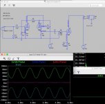
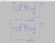
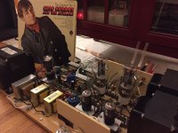
The reverse-engineered (speculatively) George Wright circuit is on the breadboard now. It’s the front end of the WPA 3.5 with a 300B output stage.
Initially the voltage was too high, so I added the lowest value/most realistic wattage dropping resistors I had on hand, a pair of 470R 5W ceramics. Voltage was uneven between the channels, and I traced it to a defective 470R resistor that was only measuring at 24.5 R. Swapped in a new one and now the channels are balanced, the 6SN7s are close to target, but the 300B B+ and plate voltage are just a little too low.
I’ve attached a screenshot of an LTSpice sim that shows the circuit at present (also a pic of the beast). The 450V DC source is from what I measured at the rectifier output. Actual voltages for the 6SN7 are about 3V higher than the ones in the model.
The 300Bs are running at about 340Vak/60mA and it sounds really good.
On Monday I’ll need to get different resistors for R23, R24, R17, and R22 to get the tube voltages correct. Targets are:
300B -- 350Vak/60mA
6SN7 -- 120Vp1, 285Vp2, 4Vk1, 125Vk2
Need to find out how to predict the amount of voltage draw out of the transformer, since it changes and then alters the whole circuit whenever I change a value somewhere.
Sounds really good, though.
Attachments
Last edited:
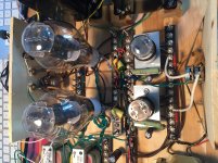
If you get some free time, can you post a few more pics of how you have built up your breadboard?
Are there still some parts stores in Tulsa?
Win W5JAG
Are there still some parts stores in Tulsa?
Win W5JAG
If you get some free time, can you post a few more pics of how you have built up your breadboard?
Are there still some parts stores in Tulsa?
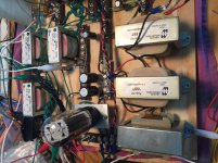
Sure! Some more breadboard pics attached. I can take more if you want.
There's a wonderful place called Affiliated Electronics where I get most of my stuff -- Electronics Parts and Components | Affiliated Electronics, Inc. HUGE selection of resistors and capacitors, though higher voltage caps (e.g. 350-630V) are tough to come by there. Lots of electromechanical and vintage stuff like terminal strips, switches, knobs, etc., too. They have a lot of unused vintage carbon comp resistors and Allen Bradley linear taper pots.
The breadboard was made mostly with stuff I had lying around in order to try various circuits and learn more about tube operation and basic electronics.
I bought a number of $0.50 screw terminal strips and mounted them with #6-32 bolts on a piece of 3/4" plywood that was lying around the garage (they are counter-sunk from underneath). There's an area for the PS rail(s) on the left, where the caps' +/- ends go across. On the right is where the 6SN7s and 300Bs (or any octal and four-pin tubes) go, with the screw strips going across. I found several octal tube sockets without mounting brackets at Affiliated, so I fabricated mounts for them out of aluminum flat bar from Home Depot and attached them with a LocTite super adhesive. They have held up perfectly well.
RCA inputs and binding posts are on a piece of 1/4" plywood mounted vertically at the back. A cheap Alpha 100K stereo volume pot is mounted on 1/4" plywood on the front. I used it for the Fi Primer and JE Labs builds, which provide enough gain that you don't need an active line preamp. Now it's disconnected because the circuit that's in it requires a line preamp.
I soldered spade lugs to transformer (including center tap) and choke leads since some of those get swapped out from time to time. Pictured here are 3 chokes on the board, a Triad C-14X (6H, 200mA, 150R) and two Hammond 159T (2.5H, 300mA, 43R), that I can swap in for various combinations and out to try different power supply configurations. The 159Ts have now been swapped out for 158Ms (10H, 100mA, 195R) in the Wright-inspired circuit.
Power transformer is a used Hammond 378CX on its own rubber-mounted block. It connects to the breadboard with lugged wires to terminal strips at the left of the PS area.
OPTs are Electra-Print 5K:8ohm, 100mA, 15W copper.
Star ground binding post is near the IEC inlet.
Insulated 600V solid copper conductor is soldered from each tube pin socket to a corresponding screw terminal. That way, I just have to unscrew/rescrew components to quickly swap out resistors or make changes without having to solder everything every time. It sounds easy but in some cases where there are several connections it's a real pain in the tush. Sometimes requires surgery-like precision with needle nose pliers and screwdriver to keep everything together as the screw pressure increases.
I also leave everything unclipped so I have full lead lengths when I use the same parts for a final build down the road. In cramped spaces I heat-shrink resistor/cap leads to avoid unwanted connections and dangerous shorts.
Obviously it's unsafe to have an unenclosed tube amp on the living room floor, so I'm currently making a nice component rack out of wood to get it out of the way. Eventually it will be replaced with a final build when I find one I want to do up.
The whole thing weighs over 50lbs.
Attachments

Last edited:
Thanks, Jeff.
Looks like you're well setup to play around with different circuits. I'm thinking on my next one that I am going to break it into two pieces - one for power supply, one for the amp.
There are some devices generally called octal relay sockets, that are basically a giant octal socket with the pins brought out to individual screw terminals, that might work for octal experimenting. I have some, but haven't tried them yet. They may not be safe for the voltage seen in tube circuits, and, mine are some kind of thermoplastic, so tube heat might be an issue, but would be handy if they can be made to work.
I think I have been to Affiliated before, it looks familiar, but it's been a long time. There used to be a decent surplus electronics dealer, don't recall exactly where, but it was on one of the main roads, off the opposite end of Memorial from the old Jaguar / Ford / Lincoln dealer.
Win W5JAG
- Status
- Not open for further replies.
- Home
- Amplifiers
- Tubes / Valves
- Modeling 300B SETs with LTSpice