I'm no so satisfied with the sound of my JBL 500 Bar and wanted to see if I can do things about it, like building a larger cabinet for the bass. So first I tried to measure the TS parameters of the subwoofer and the dimensions of the original box to model that in WinISD.
The JBL speaker has markings : S260C3C 3Ohms but it's a special reference for that subwoofer
The method I used to calculate the TS Parameters is here : https://sbacoustics.com/wp-content/uploads/2021/01/Measuring-Thiele-Small-parameters.pdf
The method I used to calculate the impedence is here : https://www.tek.com/en/documents/ho...ement-lab-measuring-impedance-and-capacitance
The results are here :


So first I'd like to know what people think of these parameters, did I made any obvious mistake or is someone willing to measure his speaker for comparaison ?
Then I went ahead to measure the enclosure. It's made of 30mm MDF at the bottom and 18mm MDF on the sides. Three faces are covered with damper. The "panel to panel" measurements are: 267mm x 267mm x 350 mm for a volume of 24.95 Liters (without removing the volume of the daming)
The vent is tricky to measure as it's an oval, and conical : The vent section Outside is like this with a section of 4475,2 mm²

The vent section inside is like that with a section of 3191,1 mm² :

As the vent has a 90° angle in the piping, I measured the longest length to be 40 cm
 and the short length to be 20 cm.
To summurize :
Vent port outside : 4475,2 mm²
Vent port inside : 3191,1 mm²
Vent long length : 40 cm
Vent short length : 20 cm
It's probably very wrong but if we assume the means, the vent average size is 3833mm² and 30 cm in length
Then in WinISD I entered the following parameters :


I do not know what are Vcd and Dvol or how important (used) they are in the software
When creating an WinISD project I entered the volume of the box : 24.95 Liters, then the vent diameter to get the same average area


Then I played with the tuning frequency in order to have WinISD calculate the vent length that is about the same size as mine : 30 cm
I'm very surprised with the results :

Did JBL really tuned a subwoofer like this and applies heavy DSP filtering ? Is that part of why I feel the JBL Bar 500 sound "Boomy" and not punchy or tight ?
Do you think I can build a larger box to make things a little better ?
Next I'll measure the frequency response of the amplifier within the subwoofer.
EDIT : I wired a 5 Ohms resistor at the output of the subwoofer amplifier module and measured amplitudes with my scope. The soundtrack generates sinusoidal tones with the sample amplitude and is played over bluetooth to the bar.

By measuring the voltage across the resistor I have an image of the gain for the whole system applied to that subwoofer
First observation: When no sound is applied there is a 385kHz sinewave with an amplitude of 1V at the terminals of the amplifier output:

This is probably the operating frequency of the D class H bridge used in this amplifier.
When I play my soundtrack overbluetooth I can plot the amplitude response of the amplifier only on it's resistor load :

We see a huge gain arround 30Hz and a band cut between 44 and 50 Hz.
Frequencies below 25 Hz are rejected by the amplifier DSP
There is a very smooth cutout frequency above 100Hz but the slope is too "weak" in my opinion and could be steeper.
This does not match exactly the spike of amplitude modeled with WinISD but I probably have many errors in my WinISD model.
Now with all these considerations, it seems that if I can build a box with the same speaker, a volume about 100L and a tuning frequency of 15Hz I can have a better low frequency response, and less of a bump at 70Hz. In red is the response with 100L box and a 15Hz tuning

The vent air speed seems to reach crasy high speeds at low frequency, however below 20Hz the JBL amplifier has a large attenuations and the speaker would never have the same excusion at these frequencies. So it might work because these air speeds are never going to be obtained in real world

I could of course make the vent larger, however the 1st port resonance would be too low...
What are your thoughs on my reasoning before I cut any piece of wood please ?
EDIT :
Link1 : https://www.diyaudio.com/community/threads/hack-for-jbl-wireless-subwoofer.413330/
Someone having issues with the amplifier and tries to add a new input to the subwoofer
Link2 : https://www.diyaudio.com/community/threads/jbl-bar-500-sub-no-power.421103/
Somone having issues with the subwoofer power supply
The JBL speaker has markings : S260C3C 3Ohms but it's a special reference for that subwoofer
The method I used to calculate the TS Parameters is here : https://sbacoustics.com/wp-content/uploads/2021/01/Measuring-Thiele-Small-parameters.pdf
The method I used to calculate the impedence is here : https://www.tek.com/en/documents/ho...ement-lab-measuring-impedance-and-capacitance
The results are here :
So first I'd like to know what people think of these parameters, did I made any obvious mistake or is someone willing to measure his speaker for comparaison ?
Then I went ahead to measure the enclosure. It's made of 30mm MDF at the bottom and 18mm MDF on the sides. Three faces are covered with damper. The "panel to panel" measurements are: 267mm x 267mm x 350 mm for a volume of 24.95 Liters (without removing the volume of the daming)
The vent is tricky to measure as it's an oval, and conical : The vent section Outside is like this with a section of 4475,2 mm²
The vent section inside is like that with a section of 3191,1 mm² :
As the vent has a 90° angle in the piping, I measured the longest length to be 40 cm
To summurize :
Vent port outside : 4475,2 mm²
Vent port inside : 3191,1 mm²
Vent long length : 40 cm
Vent short length : 20 cm
It's probably very wrong but if we assume the means, the vent average size is 3833mm² and 30 cm in length
Then in WinISD I entered the following parameters :
I do not know what are Vcd and Dvol or how important (used) they are in the software
When creating an WinISD project I entered the volume of the box : 24.95 Liters, then the vent diameter to get the same average area
Then I played with the tuning frequency in order to have WinISD calculate the vent length that is about the same size as mine : 30 cm
I'm very surprised with the results :
Did JBL really tuned a subwoofer like this and applies heavy DSP filtering ? Is that part of why I feel the JBL Bar 500 sound "Boomy" and not punchy or tight ?
Do you think I can build a larger box to make things a little better ?
Next I'll measure the frequency response of the amplifier within the subwoofer.
EDIT : I wired a 5 Ohms resistor at the output of the subwoofer amplifier module and measured amplitudes with my scope. The soundtrack generates sinusoidal tones with the sample amplitude and is played over bluetooth to the bar.
By measuring the voltage across the resistor I have an image of the gain for the whole system applied to that subwoofer
First observation: When no sound is applied there is a 385kHz sinewave with an amplitude of 1V at the terminals of the amplifier output:
This is probably the operating frequency of the D class H bridge used in this amplifier.
When I play my soundtrack overbluetooth I can plot the amplitude response of the amplifier only on it's resistor load :
We see a huge gain arround 30Hz and a band cut between 44 and 50 Hz.
Frequencies below 25 Hz are rejected by the amplifier DSP
There is a very smooth cutout frequency above 100Hz but the slope is too "weak" in my opinion and could be steeper.
This does not match exactly the spike of amplitude modeled with WinISD but I probably have many errors in my WinISD model.
Now with all these considerations, it seems that if I can build a box with the same speaker, a volume about 100L and a tuning frequency of 15Hz I can have a better low frequency response, and less of a bump at 70Hz. In red is the response with 100L box and a 15Hz tuning
The vent air speed seems to reach crasy high speeds at low frequency, however below 20Hz the JBL amplifier has a large attenuations and the speaker would never have the same excusion at these frequencies. So it might work because these air speeds are never going to be obtained in real world
I could of course make the vent larger, however the 1st port resonance would be too low...
What are your thoughs on my reasoning before I cut any piece of wood please ?
EDIT :
Link1 : https://www.diyaudio.com/community/threads/hack-for-jbl-wireless-subwoofer.413330/
Someone having issues with the amplifier and tries to add a new input to the subwoofer
Link2 : https://www.diyaudio.com/community/threads/jbl-bar-500-sub-no-power.421103/
Somone having issues with the subwoofer power supply
Attachments
Last edited:
I've just worked a little bit more on the sub and will try another software.
I wanted to see on the scope what a large drum from a battery set looked like. The kind that "thumps" when played loud.

Well it measures at 75Hz si that's maybe why the JBL subwoofer peaks arround ther in the WinISD simulations.
Taking abound software, I'll try to use from now on VituixCAD because it seems to be more up to date.
I wanted to see on the scope what a large drum from a battery set looked like. The kind that "thumps" when played loud.
Well it measures at 75Hz si that's maybe why the JBL subwoofer peaks arround ther in the WinISD simulations.
Taking abound software, I'll try to use from now on VituixCAD because it seems to be more up to date.
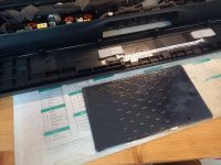
I've also taken apart the Bar to see what's inside. To open it there are about 15 visible screws on the bottom + 1 hidden screw under a cap by the HDMI connector + 2 screws hidden under the rubber feets.


Once all these screw are open slide a credit card or a mediator on the back. There is some double slided tape there.
Once opened you'll notice that :
I saw in the service manual for the JBL Bar 5 1 that standby is calculated by the microcontroller of the main board and controls a pin of the Bluetooth module.
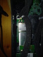
In case it could have been the case with the 500 I've checked all the pins of the Sony Wi-Fi Bluetooth module with no luck

None of the pin changes state after 10min.
Then I went on to dampen the thin plastic walls of that bar with butyl sheets. I don't really know if this will improve the overall sound. Adding mass to the walls makes them resonate much lower and absorbs the vibrations.


Once all these screw are open slide a credit card or a mediator on the back. There is some double slided tape there.
Once opened you'll notice that :
- it's well built and organized
- it has a white gasket all arround the cover to make it air tight. Keep it for closing the box again
- the plastic is very thin and makes a cheap noise.
- there are two Wi-Fi antennas on the back panels on the sides, one Bluetooth antenna in the middle of the back panel.
I saw in the service manual for the JBL Bar 5 1 that standby is calculated by the microcontroller of the main board and controls a pin of the Bluetooth module.
In case it could have been the case with the 500 I've checked all the pins of the Sony Wi-Fi Bluetooth module with no luck
None of the pin changes state after 10min.
Then I went on to dampen the thin plastic walls of that bar with butyl sheets. I don't really know if this will improve the overall sound. Adding mass to the walls makes them resonate much lower and absorbs the vibrations.
Attachments

Update: Adding Bitumen sheets inside the bar did not improve the sound as I can hear it. When hitting the plastic enclosure it with my nails it sounds dampened, but as far as the sound, the box still has resonances.
It has to be managed with the 7 bands eq of the JBL One app.
It has to be managed with the 7 bands eq of the JBL One app.
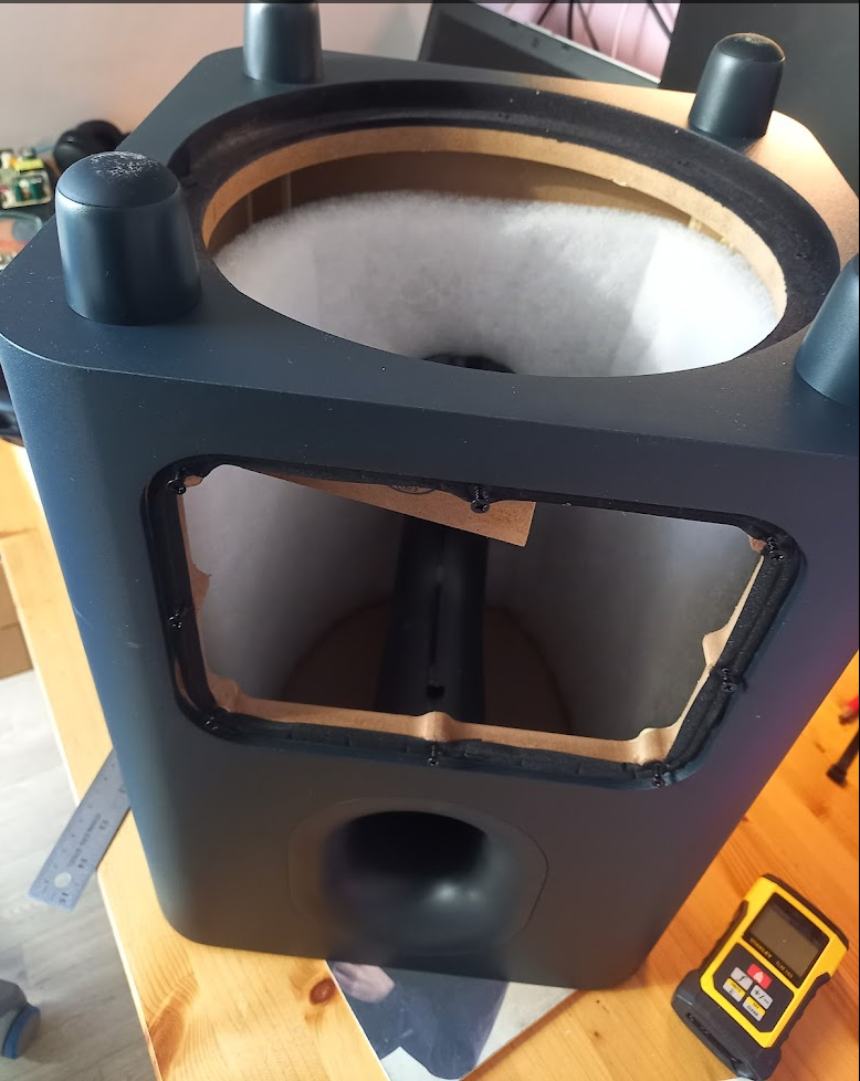
Updates, I finished the new subwoofer enclosure:


After transfering the speaker and the amplifier board it tested pretty well. Deep bass are much more pronounced and there is less of a "boomy" sound to it.
This is my final winISD simulation with the actual dimensions of the enclosure and the vent:


If you have the courage to build up your own enclosure I would say it definitely is worth it. Bitumen in the bar was a waste of time but the larger enclosure brings something that the original subwoofer was not capable of doing;
These are the two posts on the JBL Facebook group:
https://www.facebook.com/groups/998339600582509/posts/2247484439001346/
https://www.facebook.com/groups/998339600582509/posts/2261823074234149/
Issues I need to fix : The amplifier "plate" is kind of weak, it's a cheap plastic plate with maybe 1 or 2 mm thickness. It is soft and I leak air arround it because I haven't made the opening in the wood correctly with my router. I'm going to fix the air leaks arround it, and maybe find ways to make the plate more rigid.
What's the point of using 3/4 OSB with internal bracings if there is a plastic plate on the rear side... 🙂
After transfering the speaker and the amplifier board it tested pretty well. Deep bass are much more pronounced and there is less of a "boomy" sound to it.
This is my final winISD simulation with the actual dimensions of the enclosure and the vent:
If you have the courage to build up your own enclosure I would say it definitely is worth it. Bitumen in the bar was a waste of time but the larger enclosure brings something that the original subwoofer was not capable of doing;
These are the two posts on the JBL Facebook group:
https://www.facebook.com/groups/998339600582509/posts/2247484439001346/
https://www.facebook.com/groups/998339600582509/posts/2261823074234149/
Issues I need to fix : The amplifier "plate" is kind of weak, it's a cheap plastic plate with maybe 1 or 2 mm thickness. It is soft and I leak air arround it because I haven't made the opening in the wood correctly with my router. I'm going to fix the air leaks arround it, and maybe find ways to make the plate more rigid.
What's the point of using 3/4 OSB with internal bracings if there is a plastic plate on the rear side... 🙂
Last edited: