The CPU is upside down and uses its shield to transfer heat to that plate. Best would be to glue a heatsink to the CPU but then the shield must be cut with a dremel. Would be the most effective solution.
I must admit I put it together but i forgot the exact sequence of shield/plate 🙂 Seems right when I think of it.
Your solution also works but then you must drill the holes in the plate slightly larger as they can misalign somewhat. The holes will be in sight which may even be worse than my work although that is hard to beat 😉
Last edited:
J-P,
Do you have a schematic for this power supply?
Thanks,
Nick
Hi I use a ready made PSU board of a vendor here. This is a temporary solution as I am designing a high current LDO (not with LT3045).
Last edited:
I really have too many projects going on right now to tackle this also.
Anyone interested in buying mine? It's a beige version B. Fully operational, comes with internal 256GB SSD full with music ;-)
Jan
Anyone interested in buying mine? It's a beige version B. Fully operational, comes with internal 256GB SSD full with music ;-)
Jan
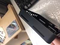
Ok, it took a while but I modified 3 casings and this is the best till now. This was done by a professional CNC guy. The heat difference between a modified casing and the original one is 10 to 15 degrees Celsius easily. Regardless of the shape of the cooling vents I never measure higher than 40 degrees on the upper side of the Mini.
The original linear PSU performed excellent. I closely inspected it and besides an LM317 as preregulator (I think...) it has a TPS7A4700 as regulator. Fine design but no feet so easily scratched and the mains switch is at the back. This combined with the relatively high price made me sell it and build a DIY version. I made 4 different linear low noise LDO 15V PSU's for it. All are way better than the 16V switcher that is with the device originally.
Why people still bother with CD's and worn out lasers in CD players is beyond me when you can have so much sound quality for such a little price. Operating the device is very easy.
Attachments
Last edited:
Hi.
Are you aware of a cooling paste coupling that also has a gluing behavior please ? I am thinking aboutcopper top plate as shielding AND cooling...certainly more micro holes will work better Emc/ime than few bigger ones...Dremel job...
Are you aware of a cooling paste coupling that also has a gluing behavior please ? I am thinking aboutcopper top plate as shielding AND cooling...certainly more micro holes will work better Emc/ime than few bigger ones...Dremel job...
Yes I am aware that thermal glue exists and I use nothing else when using heatsinks on ICs (no paste for me). However, if I understand correctly what you mean, your solution is not a real solution as heat buildup is like it is because the casing is fully closed. Even if you get rid of the heat of the CPU there still are other parts generating heat inside the plastic casing. Ventilation is absolutely needed to let the heat out. IF you want to add a heatsink on top it better make good direct contact with the metal mounting plate/heatsink. The plastic of the white version is very brittle when it is already yellow so please watch out and work carefully.
About the holes: larger holes allow better airflow. No need to worry about EMI. The top plate is metal and other EMI generating parts are shielded the way it was done in older FM tuners. The Aries Mini has exemplary shielding of EMI generating electronics!
About the holes: larger holes allow better airflow. No need to worry about EMI. The top plate is metal and other EMI generating parts are shielded the way it was done in older FM tuners. The Aries Mini has exemplary shielding of EMI generating electronics!
Last edited:
Thermaltake Arctic Alumina is the one. I think it is out of production now so I bought a few syringes. Very good stuff.
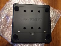
Meant for glueing aluminium heatsinks to ICs etc. In the case or Aries Mini there is a thick plastic upper cover between the top plate that also serves as heatsink. Any new construction should transfer the heat from the heatsink to the outside. With a layer plastic in between this will not be optimal. Surface of the top plate is OK, just add a few holes at the bottom (also through the SSD bracket) and at the sides of the upper cover.
Meant for glueing aluminium heatsinks to ICs etc. In the case or Aries Mini there is a thick plastic upper cover between the top plate that also serves as heatsink. Any new construction should transfer the heat from the heatsink to the outside. With a layer plastic in between this will not be optimal. Surface of the top plate is OK, just add a few holes at the bottom (also through the SSD bracket) and at the sides of the upper cover.
Last edited:
Like this. Please note the elevated rubber feet (for better convection) and the holes near them. That is where wireless electronics are which also heat up.
Removing the bottom cover is easy peasy. The hard part is removing the electronics from the upper cover. Please make sure you have a "fresh" Torx screwdriver as the stainless screws are tightened extremely and strip very easy. In fact you may damage them at the first try. It is best to replace them for normal Philips or Pozidriv types made of galvanised steel.
Removing the bottom cover is easy peasy. The hard part is removing the electronics from the upper cover. Please make sure you have a "fresh" Torx screwdriver as the stainless screws are tightened extremely and strip very easy. In fact you may damage them at the first try. It is best to replace them for normal Philips or Pozidriv types made of galvanised steel.
Attachments
Last edited:
Thermaltake Arctic Alumina is the one. I think it is out of production now so I bought a few syringes. Very good stuff.
Meant for glueing aluminium heatsinks to ICs etc. In the case or Aries Mini there is a thick plastic upper cover between the top plate that also serves as heatsink. Any new construction should transfer the heat from the heatsink to the outside. With a layer plastic in between this will not be optimal. Surface of the top plate is OK, just add a few holes at the bottom (also through the SSD bracket) and at the sides of the upper cover.
Thanks for that, appreciated, I have to drop a Mouser otder and need that without knowing a thermal glue existed but the usual white paste that needs screw and heatsink on it... I want to make some ic shielding, clock, dac, etc with copper plate !
OK, please note that removing a glued heatsink means the IC also comes off the PCB. Make sure the surfaces are flush and clean them thoroughly with isopropyl alcohol.
I would like to keep things on topic. Please. It is obvious you are not meaning Aries Mini as EMI generating parts are shielded already.
I would like to keep things on topic. Please. It is obvious you are not meaning Aries Mini as EMI generating parts are shielded already.
Last edited:
Anyone also busy with modding these? I definitely can recommend doing something with better ventilation/convection as I already had defective Aries Mini at hand. Because of the extreme heat inside the analog channels start crackling and this is a nasty repair. Also a PSU that can be switched off is recommended with around 6W power consumption when idling!
Soundwise the product still is competitive with current devices on the market.
Soundwise the product still is competitive with current devices on the market.
Last edited:
Hi Jean-Paul,
a couple of months ago I purchased a black one 2nd hand with a snapped of RCA plug. Would it be possible to solder a new RCA plug on?
Currently i use the USB output to a Pro-Ject pre box digital S2 DAC.
Once open, I will try to drill some venting holes as well since my DAC sits on top of the Aries mini.
Thanks,
Joris
Yes that is possible certainly when you obtain the same RCA connectors. With regards to the heat: try to drill 5 or 6 mm holes where the heat occurs. I studied on this carefully so you can use the spots as determined to have impact, most important are the backside ones. Just take a look at the pictures.
I hope yours is still 100% OK as these devices have dying DAC chips because of the heat. This counts more for the ones that are used with the original PSU as they are then powered on 24/7.
The same tip again: be very careful to use a "fresh" Torx screw driver as the stainless steel Torx screw easily strip. Replace for identical normal steel screws.
Last edited:
Thanks for your quick reply and your tps regarding dying DAC. Mine is powered on 24/7 by a Sbooster 15-16V PSU. So I guess the heat is a serious issue.
Managed to find a 3 way RCA pcb connector on Mouser, which I just ordered and I’ll see if it fits.
Joris
Managed to find a 3 way RCA pcb connector on Mouser, which I just ordered and I’ll see if it fits.
Joris
If Sbooster has a mains switch then please use it. The device consumes approx.7 to 8W (in idle!) if I remember correctly. Apart from the heat buildup around CPU and wireless module it serves little purpose keeping it powered on 24/7. The main complaint is just 1 of the channels making scratching noises and static noise/crackling.
If you use a sharp good quality sidecutter you can totally destroy the original connectors plastic parts without even scratching the PCB. Then only the metal parts are left which can be removed relatively easy with a 80W soldering tool. Try to heat the PCB fast and hot. The material is not as weak as usual which helps 🙂
If you use a sharp good quality sidecutter you can totally destroy the original connectors plastic parts without even scratching the PCB. Then only the metal parts are left which can be removed relatively easy with a 80W soldering tool. Try to heat the PCB fast and hot. The material is not as weak as usual which helps 🙂
Last edited:
- Home
- Source & Line
- Digital Source
- Modding AURALiC Aries Mini